


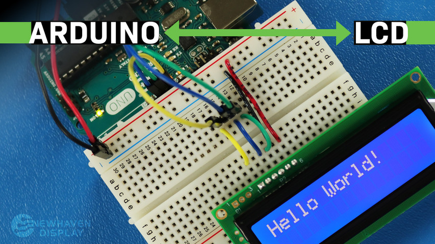
Como ligar o LCD ao Arduino
19 de maio de 2023
O LCD (Ecrã de Cristais Líquidos) é um ecrã frequentemente utilizado em projetos com Arduino, uma vez que oferece uma forma simples de apresentar informações ao utilizador, tais como texto e caracteres básicos. É um ecrã útil tanto para principiantes como para utilizadores experientes e é, normalmente, um dos primeiros ecrãs que as pessoas utilizam quando começam a utilizar uma placa Arduino.
Este tutorial irá mostrar-lhe como ligar e estabelecer comunicação entre um ecrã LCD de caracteres 16x2 e uma placa Arduino UNO, utilizando comunicação série.
Os princípios apresentados neste tutorial podem ser aplicados também a outros ecrãs LCD e a outras placas de desenvolvimento. Vamos começar!
LCD - Tutorial do Arduino - Índice
- Material e ferramentas necessárias
- Disposição dos pinos do LCD
- Disposição dos pinos do Arduino
- Circuito - diagrama de ligação e esquema para comunicação SPI
- Código de exemplo que utiliza a interface SPI
- Olá, mundo!
- Mostrar o texto na primeira e na segunda linha
- Mostrar texto descritivo
- Blink - Mostrar texto com um cursor intermitente
- Cursor + texto com deslocamento automático
- Texto com deslocamento automático
- Ajustar o contraste do ecrã LCD
- Como utilizar a retroiluminação do ecrã LCD
- Tabelas de caracteres/tipos de letra
- Circuito - diagrama de ligação e esquema para comunicação RS232 TTL
- «Olá, Mundo!» – código de exemplo utilizando a interface RS232 TTL
- Resolução de problemas do seu LCD - Projeto Arduino
- Recursos adicionais
Material e ferramentas necessárias
Os ecrãs LCD estão disponíveis em vários tamanhos e configurações, mas o mais utilizado é o LCD 16x2. Possui 2 linhas, cada uma com capacidade para 16 caracteres.
Iremos utilizar o ecrã Newhaven 16x2, com o número de referência NHD-0216K3Z-NSW-BBW-V3, que possui um microcontrolador PIC16F690 integrado. Este LCD suporta três interfaces seriais: I2C, SPI e RS-232 (TTL). Este artigo irá centrar-se nas interfaces SPI e RS-232 e fornecer exemplos de código para ambas.
Este ecrã está disponível para compra aqui. A ficha técnica e as especificações do produto podem ser consultadas ou descarregadas aqui.
Tenha em atenção que a utilização da interface SPI requer a soldadura de um resistor ao ecrã, ao passo que a interface RS-232 TTL não o requer. Por conseguinte, se preferir seguir este tutorial sem soldar o resistor, pode seguir as instruções relativas à interface RS-232 TTL e a secção de exemplos de código.
O que vai precisar para ligar o Arduino a um ecrã LCD
- LCD 16x2
- Conector de pinos de uma só fila
- Arduino UNO
- placa de ensaio
- Fios de ligação
- Solda e ferro de soldar
- Cabo USB A macho para B macho (cabo de impressora)
- IDE do Arduino
- Resistência de 0 ohms (opcional — apenas para comunicação SPI)
Sugerimos que leia o artigo do nosso blogue intitulado «Como proteger os equipamentos eletrónicos contra descargas eletrostáticas» antes de avançar para este tutorial, especialmente se for um principiante na área da eletrónica.
Configuração dos pinos do LCD 16x2
O ecrã LCD de 16x2 caracteres da Newhaven oferece uma forma simples de interagir com a placa Arduino UNO através de comunicação série. Os pinos da porta P1 foram especificamente concebidos para comunicação série RS232 TTL, enquanto os pinos da porta P2 se destinam à comunicação série I2C e SPI.
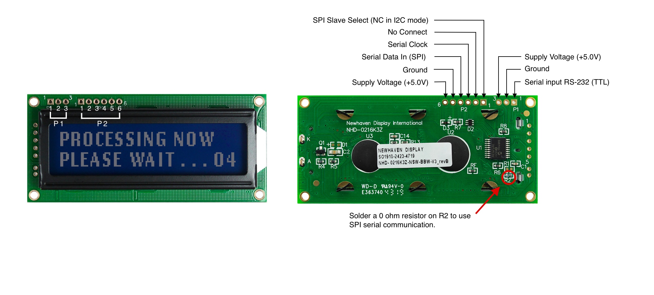
Descrição dos pinos P1 - Comunicação RS232 TTL
| N.º do pino | Símbolo | Descrição da função |
|---|---|---|
| 1 | RX | Entrada série RS-232 (TTL) |
| 2 | V SS | Terreno |
| 3 | V DD | Tensão de alimentação (+5,0 V) |
Descrição dos pinos P2 - Comunicação SPI e I2C
| N.º do pino | Símbolo | Descrição da função |
|---|---|---|
| 1 | SPISS | Seleção de Escravo SPI (NC no modo I2C) |
| 2 | SDO | Sem ligação |
| 3 | SCK/SCL | Relógio em série |
| 4 | SDI/SDA | Entrada de dados em série (SPI) / Dados em série (I2C) |
| 5 | V SS | Terreno |
| 6 | V DD | Tensão de alimentação (+5,0 V) |
A especificação completa da disposição dos pinos do ecrã LCD pode ser consultada aqui.
Disposição dos pinos do Arduino
A placa Arduino UNO possui 20 pinos de entrada/saída, incluindo 14 pinos digitais e 6 pinos analógicos, e, para este projeto, iremos utilizar os pinos de 5 V e GND dos sinais de alimentação, os pinos 10, 11 e 12 para SPI ou I2C e o pino 7 para RS232 TTL.
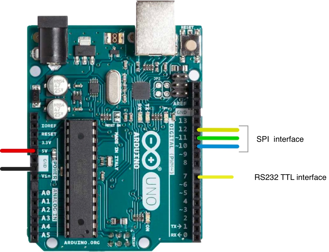
O esquema completo da disposição dos pinos do Arduino UNO pode ser consultado aqui.
Circuito - Diagrama de ligações e esquema para comunicação SPI
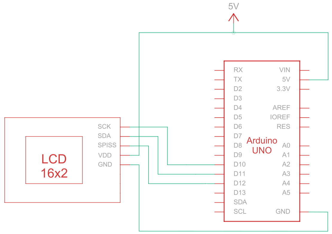
A Interface Periférica Serial (SPI) é um barramento de comunicação serial síncrono utilizado para comunicação de curta distância e alta velocidade entre vários dispositivos. O circuito de ligação para a comunicação SPI entre o Arduino (dispositivo mestre) e o LCD (dispositivo escravo) utiliza cinco fios para a comunicação, conforme descrito na tabela abaixo:
| Arduino | LCD | Tipo de ligação |
|---|---|---|
| Pino de 5 V | Pino 6: V DD | Potência |
| Pino de terra | Pino 5: Terra | Terreno |
| Pino 10: Seleção de escravo | Pino 3: SCK/SCL | Relógio em série |
| Pino 11: MISO | Pino 4: Entrada de dados em série (SPI) / Dados em série (I2C) | Entrada de dados em série |
| Pino 12: MOSI | Pino 1: SPISS | Seleção de Escravo SPI |
Nota:
Para ativar o SPI, é necessário que R1 esteja aberto e que R2 seja encurtado, conforme especificado na ficha técnica. Além disso, antes de começar, certifique-se de que o Arduino está desligado enquanto liga o circuito.
Circuito de ligação do SPI
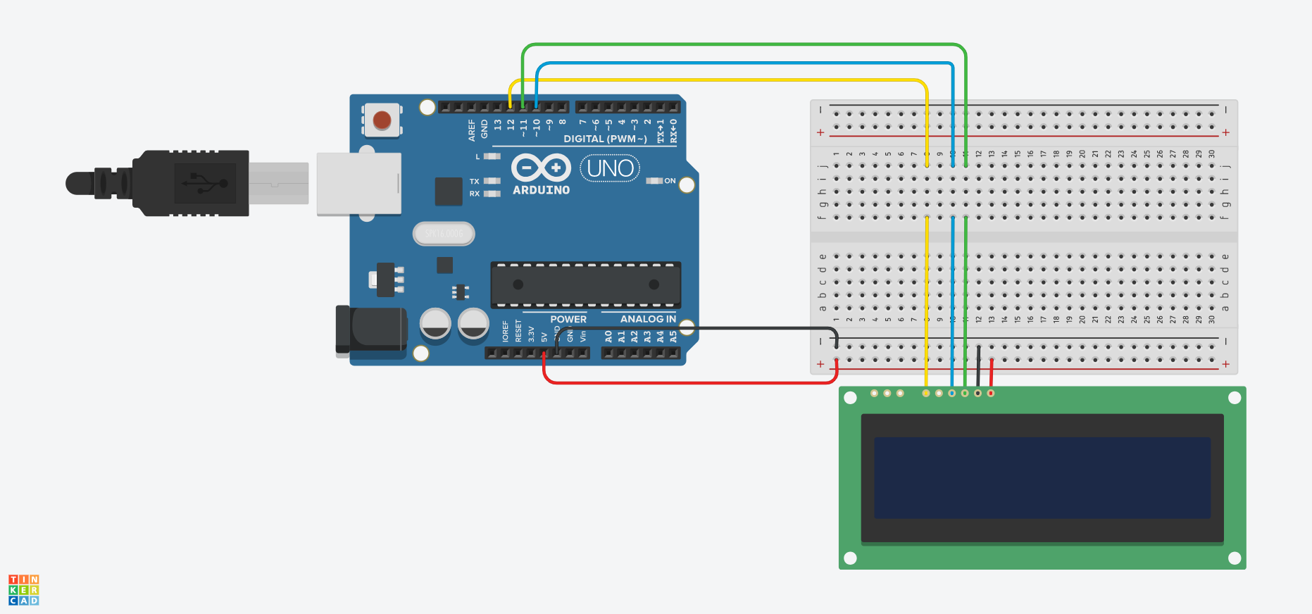
Esquema de ligações do SPI
Arduino - Código de exemplo para ecrã LCD utilizando a interface SPI
Os exemplos de código que se seguem demonstram como utilizar a comunicação série entre o Arduino e um ecrã LCD de 16x2 caracteres através da interface SPI. Encontrará comentários úteis nos exemplos de código, mas vamos analisar algumas das funções abaixo:
- O
SPI_Out()A função envia comandos e dados para o ecrã LCD através da interface SPI. Para tal, percorre os 8 bits do byte de entrada e envia o valor de cada bit para o ecrã LCD. - O
Set_Pins()A função configura os pinos SPI como pinos de saída. - O
Set_Contrast()Esta função define o contraste do ecrã LCD. - O
Set_Backlight()Esta função define a retroiluminação do ecrã LCD. - O
Clear_Display()Esta função limpa o ecrã LCD. - O
Set_Cursor()Esta função ativa ou desativa o cursor intermitente no ecrã LCD, dependendo do parâmetro de entrada. - O
setup()A função é a função principal e é executada uma vez quando o Arduino arranca. É utilizada para inicializar as definições, as variáveis e para executar quaisquer outras funções e configurações necessárias para o projeto. - O
loop()A função é executada num ciclo contínuo durante todo o tempo em que a placa Arduino estiver ligada. Em alguns dos exemplos abaixo, esta função está vazia e não faz nada, porque só precisamos de executar algumas funções uma única vez.
Arduino - Exemplos de código para ecrãs LCD utilizando SPI:
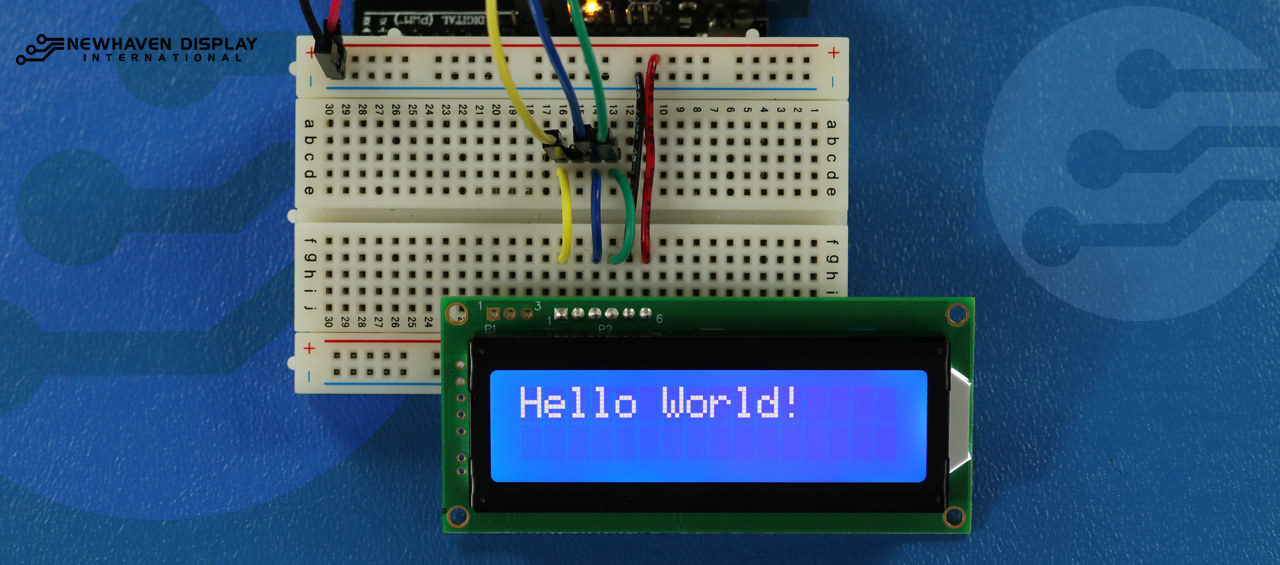
- Olá, mundo!
- Mostrar o texto na primeira e na segunda linha
- Mostrar texto descritivo
- Mostrar texto com um cursor intermitente
- Cursor + texto com deslocamento automático
- Deslocamento automático
- Contraste
- Retroiluminação
- Tabelas de caracteres/tipos de letra
Pode adaptar e ampliar os exemplos de código de forma a satisfazer os requisitos específicos do seu projeto baseado em Arduino.
Olá, mundo!
O exemplo de código seguinte exibe «Hello Word!» no ecrã LCD.
/*  SPI Wiring Reference for: NHD-0216K3Z-NSW-BBW-V3
  ---------------------------
  LCD         |   Arduino
  ---------------------------
  1(SPISS)  --> 12
  2(SDO)    --> No Connect
  3(SCK)    --> 10
  4(SDA)    --> 11
  5(VSS)    --> Ground
  6(VDD)    --> 5V
*/
/*****************************************************
   Arduino pin definition
  /*****************************************************/
#define SPISS_PIN   12
#define SDA_PIN     11
#define SCK_PIN     10
/*****************************************************
   SPI function to send command and data.
   For more information on SPI please visit our Support Center
  /*****************************************************/
void SPI_Out(unsigned char a) {
  digitalWrite(SPISS_PIN, LOW);
  for (int n = 0; n < 8; n++) {
    if ((a & 0x80) == 0x80) {
      digitalWrite(SDA_PIN, HIGH);
      delayMicroseconds(200);
    }
    else {
      digitalWrite(SDA_PIN, LOW);
    }
    delayMicroseconds(200);
    a = a << 1;
    digitalWrite(SCK_PIN, LOW);
    digitalWrite(SCK_PIN, HIGH);
    delayMicroseconds(200);
  }
  digitalWrite(SCK_PIN, HIGH);
  delayMicroseconds(200);
  digitalWrite(SPISS_PIN, HIGH);
}
/*****************************************************
   Set Arduino UNO IO ports as Output mode
  /*****************************************************/
void Set_Pins() {
  pinMode(SPISS_PIN, OUTPUT);
  pinMode(SCK_PIN, OUTPUT);
  pinMode(SDA_PIN, OUTPUT);
}
/*****************************************************
   Set LCD Contrast
  /*****************************************************/
void Set_Contrast() {
  SPI_Out(0xFE);              //prefix command
  SPI_Out(0x52);              //contrast command
  SPI_Out(0x28);              //set contrast value
  delayMicroseconds(500);
}
/*****************************************************
   Set LCD Backlight
  /*****************************************************/
void Set_Backlight() {
  SPI_Out(0xFE);             //prefix command
  SPI_Out(0x53);             //backlight command
  SPI_Out(0x08);             //set backlight value
  delayMicroseconds(100);
}
/*****************************************************
   Clear LCD
  /*****************************************************/
void Clear_Display() {
  SPI_Out(0xFE);             //prefix command
  SPI_Out(0x51);             //clear display command
  delayMicroseconds(1500);
}
/*****************************************************
   Set cursor
   Mode = 0 sets Blinking cursor off
   Mode = 1 sets Blinking cursor on
  /*****************************************************/
void Set_Cursor(int mode) {
  SPI_Out(0xfe);          //prefix command
  if (mode == 0) {
    SPI_Out(0x4c);        //Blinking cursor off
  }
  else if (mode == 1) {
    SPI_Out(0x4b);        //Blinking cursor on
  }
  delayMicroseconds(100);
}
/*****************************************************
   Write "Hello World!" to LCD
  /*****************************************************/
void Hello_World() {
  SPI_Out(0x48); // H
  SPI_Out(0x65); // E
  SPI_Out(0x6C); // l
  SPI_Out(0x6C); // l
  SPI_Out(0x6F); // o
  SPI_Out(0x11); // Blank
  SPI_Out(0x57); // W
  SPI_Out(0x6f); // o
  SPI_Out(0x72); // r
  SPI_Out(0x6c); // l
  SPI_Out(0x64); // d
  SPI_Out(0x21); // !
}
/*****************************************************
     Main function
  /*****************************************************/
void setup() {
  Set_Pins();         //set IO ports
  Set_Cursor(0);      //turns off blinking cursor
  Set_Contrast();     //set display contrast
  Set_Backlight();    //set display backlight
  Clear_Display();    //clear display
  Hello_World();      //display "Hello World!"
}
void loop() {
}
Mostrar o texto na primeira e na segunda linha
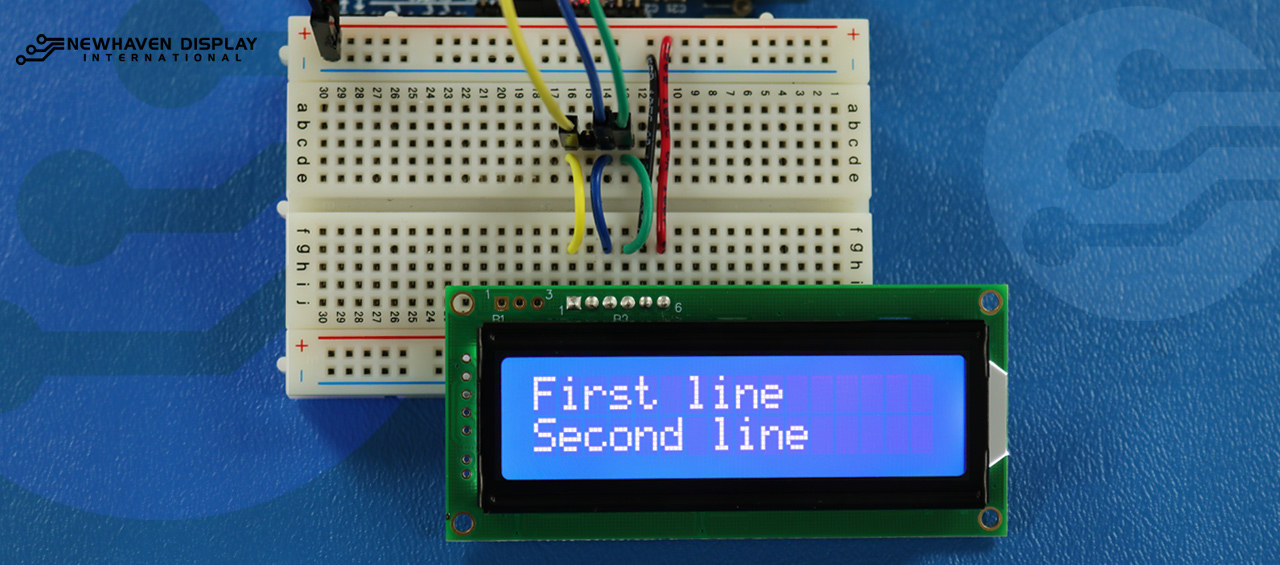
Este código irá apresentar o texto «Primeira linha» na primeira linha e «Segunda linha» na segunda linha.
/*****************************************************
  This code was written for the Arduino UNO using SPI Interface.
  This code displays text in row one and row two of LCD.
  /*  SPI Wiring Reference for: NHD-0216K3Z-NSW-BBW-V3
  ---------------------------
  LCD         |   Arduino
  ---------------------------
  1(SPISS)  --> 12
  2(SDO)    --> No Connect
  3(SCK)    --> 10
  4(SDA)    --> 11
  5(VSS)    --> Ground
  6(VDD)    --> 5V
*/
/*****************************************************
   Arduino pin definition
  /*****************************************************/
#define SPISS_PIN   12
#define SDA_PIN     11
#define SCK_PIN     10
/*****************************************************
   SPI function to send command and data.
   For more information on SPI please visit our Support Center
  /*****************************************************/
void SPI_Out(unsigned char a) {
  digitalWrite(SPISS_PIN, LOW);
  for (int n = 0; n < 8; n++) {
    if ((a & 0x80) == 0x80) {
      digitalWrite(SDA_PIN, HIGH);
      delayMicroseconds(200);
    }
    else {
      digitalWrite(SDA_PIN, LOW);
    }
    delayMicroseconds(200);
    a = a << 1;
    digitalWrite(SCK_PIN, LOW);
    digitalWrite(SCK_PIN, HIGH);
    delayMicroseconds(200);
  }
  digitalWrite(SCK_PIN, HIGH);
  delayMicroseconds(200);
  digitalWrite(SPISS_PIN, HIGH);
}
/*****************************************************
   Set Arduino UNO IO ports as Output mode
  /*****************************************************/
void Set_Pins() {
  pinMode(SPISS_PIN, OUTPUT);
  pinMode(SCK_PIN, OUTPUT);
  pinMode(SDA_PIN, OUTPUT);
}
/*****************************************************
   Set LCD Contrast
  /*****************************************************/
void Set_Contrast() {
  SPI_Out(0xFE);              //prefix command
  SPI_Out(0x52);              //contrast command
  SPI_Out(0x28);              //set contrast value
  delayMicroseconds(500);
}
/*****************************************************
   Set LCD Backlight
  /*****************************************************/
void Set_Backlight() {
  SPI_Out(0xFE);             //prefix command
  SPI_Out(0x53);             //backlight command
  SPI_Out(0x08);             //set backlight value
  delayMicroseconds(100);
}
/*****************************************************
   Clear LCD
  /*****************************************************/
void Clear_Display() {
  SPI_Out(0xFE);             //prefix command
  SPI_Out(0x51);             //clear display command
  delayMicroseconds(1500);
}
/*****************************************************
   Write "First Line" to row one on LCD
  /*****************************************************/
void Send_First_Line_Text() {
  SPI_Out(0x46); // F
  SPI_Out(0x69); // i
  SPI_Out(0x72); // r
  SPI_Out(0x73); // s
  SPI_Out(0x74); // t
  SPI_Out(0x20); // blank space
  SPI_Out(0x6c); // l
  SPI_Out(0x69); // i
  SPI_Out(0x6e); // n
  SPI_Out(0x65); // e
}
/*****************************************************
   Write "Second Line" to row two on LCD
  /*****************************************************/
void Send_Second_Line_Text() {
  SPI_Out(0x53); // S
  SPI_Out(0x65); // e
  SPI_Out(0x63); // c
  SPI_Out(0x6f); // o
  SPI_Out(0x6e); // n
  SPI_Out(0x64); // d
  SPI_Out(0x20); // blank space
  SPI_Out(0x6c); // l
  SPI_Out(0x69); // i
  SPI_Out(0x6e); // n
  SPI_Out(0x65); // e
}
/*****************************************************
   Set Row address
   Line = 1 sets for first row
   Line = 2 sets for second row
  /*****************************************************/
void Set_Row(int line) {
  SPI_Out(0xfe);      //prefix command
  SPI_Out(0x45);      //set cursor command
  if (line == 1) {
    SPI_Out(0x00);    //cursor position: row one, column one
  }
  else if (line == 2) {
    SPI_Out(0x40);    //cursor position: row two, column one
  }
  delayMicroseconds(100);
}
/*****************************************************
     Main function
  /*****************************************************/
void setup() {
  Set_Pins();         //set IO ports
  Set_Contrast();     //set display contrast
  Set_Backlight();    //set display backlight
  Clear_Display();    //clear display
  Set_Row(1);
  Send_First_Line_Text();       //writes to first line of display
  Set_Row(2);
  Send_Second_Line_Text();      //writes to second line of display
  delay(1000);
}
void loop() {
}
Mostrar texto descritivo
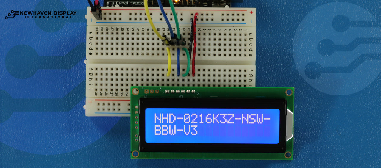
Este código apresenta um texto que se estende até à segunda linha. Neste exemplo, vamos apresentar o texto «NHD-0216K3Z-NSW-BBW-V3».
/*****************************************************
  This code displays the part number: NHD-0216K3Z-NSW-BBW-V3.
  /*  SPI Wiring Reference for: NHD-0216K3Z-NSW-BBW-V3
  ---------------------------
  LCD         |   Arduino
  ---------------------------
  1(SPISS)  --> 12
  2(SDO)    --> No Connect
  3(SCK)    --> 10
  4(SDA)    --> 11
  5(VSS)    --> Ground
  6(VDD)    --> 5V
*/
/*****************************************************
   Arduino pin definition
  /*****************************************************/
#define SPISS_PIN   12
#define SDA_PIN     11
#define SCK_PIN     10
/*****************************************************
   SPI function to send command and data.
   For more information on SPI please visit our Support Center
  /*****************************************************/
void SPI_Out(unsigned char a) {
  digitalWrite(SPISS_PIN, LOW);
  for (int n = 0; n < 8; n++) {
    if ((a & 0x80) == 0x80) {
      digitalWrite(SDA_PIN, HIGH);
      delayMicroseconds(200);
    }
    else {
      digitalWrite(SDA_PIN, LOW);
    }
    delayMicroseconds(200);
    a = a << 1;
    digitalWrite(SCK_PIN, LOW);
    digitalWrite(SCK_PIN, HIGH);
    delayMicroseconds(200);
  }
  digitalWrite(SCK_PIN, HIGH);
  delayMicroseconds(200);
  digitalWrite(SPISS_PIN, HIGH);
}
/*****************************************************
   Set Arduino UNO IO ports as Output mode
  /*****************************************************/
void Set_Pins() {
  pinMode(SPISS_PIN, OUTPUT);
  pinMode(SCK_PIN, OUTPUT);
  pinMode(SDA_PIN, OUTPUT);
}
/*****************************************************
   Set LCD Contrast
  /*****************************************************/
void Set_Contrast() {
  SPI_Out(0xFE);              //prefix command
  SPI_Out(0x52);              //contrast command
  SPI_Out(0x28);              //set contrast value
  delayMicroseconds(500);
}
/*****************************************************
   Set LCD Backlight
  /*****************************************************/
void Set_Backlight() {
  SPI_Out(0xFE);             //prefix command
  SPI_Out(0x53);             //backlight command
  SPI_Out(0x08);             //set backlight value
  delayMicroseconds(100);
}
/*****************************************************
   Clear LCD
  /*****************************************************/
void Clear_Display() {
  SPI_Out(0xFE);             //prefix command
  SPI_Out(0x51);             //clear display command
  delayMicroseconds(1500);
}
/*****************************************************
   Set cursor
   Mode = 0 sets Blinking cursor off
   Mode = 1 sets Blinking cursor on
  /*****************************************************/
void Set_Cursor(int mode) {
  SPI_Out(0xfe);          //prefix command
  if (mode == 0) {
    SPI_Out(0x4c);        //Blinking cursor off
  }
  else if (mode == 1) {
    SPI_Out(0x4b);        //Blinking cursor on
  }
  delayMicroseconds(100);
}
/*****************************************************
   Set Row address
   Line = 1 sets for first row
   Line = 2 sets for second row
  /*****************************************************/
void Set_Row(int line) {
  SPI_Out(0xfe);      //prefix command
  SPI_Out(0x45);      //set cursor command
  if (line == 1) {
    SPI_Out(0x00);    //cursor position: row one, column one
  }
  else if (line == 2) {
    SPI_Out(0x40);    //cursor position: row two, column one
  }
  delayMicroseconds(100);
}
/*****************************************************
   Write "NHD-0216K3Z-NSW-BBW-V3" to LCD
  /*****************************************************/
void Part_Number() {
  Set_Row(1);
  SPI_Out(0x4e); // N
  SPI_Out(0x48); // H
  SPI_Out(0x44); // D
  SPI_Out(0xb0); // -
  SPI_Out(0x30); // 0
  SPI_Out(0x32); // 2
  SPI_Out(0x31); // 1
  SPI_Out(0x36); // 6
  SPI_Out(0x4b); // K
  SPI_Out(0x33); // 3
  SPI_Out(0x5a); // Z
  SPI_Out(0xb0); // -
  SPI_Out(0x4e); // N
  SPI_Out(0x53); // S
  SPI_Out(0x57); // W
  SPI_Out(0xb0); // -
  Set_Row(2);
  SPI_Out(0x42); // B
  SPI_Out(0x42); // B
  SPI_Out(0x57); // W
  SPI_Out(0xb0); // -
  SPI_Out(0x56); // V
  SPI_Out(0x33); // 3
}
/*****************************************************
     Main function
  /*****************************************************/
void setup() {
  Set_Pins();         //set IO ports
  Set_Cursor(0);      //turns off blinking cursor
  Set_Contrast();     //set display contrast
  Set_Backlight();    //set display backlight
  Clear_Display();    //clear display
  Part_Number();      //display "NHD-0216K3Z-NSW-BBW-V3"
}
void loop() {
}
Blink - Mostrar texto com o cursor a piscar
Este código apresenta texto com um cursor intermitente. Neste exemplo, vamos apresentar o textoNHD-0216K3Z-NSW-BBW-V3».
/*****************************************************
  This code displays the part number: NHD-0216K3Z-NSW-BBW-V3 with cursor on.
  /*  SPI Wiring Reference for: NHD-0216K3Z-NSW-BBW-V3
  ---------------------------
  LCD         |   Arduino
  ---------------------------
  1(SPISS)  --> 12
  2(SDO)    --> No Connect
  3(SCK)    --> 10
  4(SDA)    --> 11
  5(VSS)    --> Ground
  6(VDD)    --> 5V
*/
/*****************************************************
   Arduino pin definition
  /*****************************************************/
#define SPISS_PIN   12
#define SDA_PIN     11
#define SCK_PIN     10
/*****************************************************
   SPI function to send command and data.
   For more information on SPI please visit our Support Center
  /*****************************************************/
void SPI_Out(unsigned char a) {
  digitalWrite(SPISS_PIN, LOW);
  for (int n = 0; n < 8; n++) {
    if ((a & 0x80) == 0x80) {
      digitalWrite(SDA_PIN, HIGH);
      delayMicroseconds(200);
    }
    else {
      digitalWrite(SDA_PIN, LOW);
    }
    delayMicroseconds(200);
    a = a << 1;
    digitalWrite(SCK_PIN, LOW);
    digitalWrite(SCK_PIN, HIGH);
    delayMicroseconds(200);
  }
  digitalWrite(SCK_PIN, HIGH);
  delayMicroseconds(200);
  digitalWrite(SPISS_PIN, HIGH);
}
/*****************************************************
   Set Arduino UNO IO ports as Output mode
  /*****************************************************/
void Set_Pins() {
  pinMode(SPISS_PIN, OUTPUT);
  pinMode(SCK_PIN, OUTPUT);
  pinMode(SDA_PIN, OUTPUT);
}
/*****************************************************
   Set LCD Contrast
  /*****************************************************/
void Set_Contrast() {
  SPI_Out(0xFE);              //prefix command
  SPI_Out(0x52);              //contrast command
  SPI_Out(0x28);              //set contrast value
  delayMicroseconds(500);
}
/*****************************************************
   Set LCD Backlight
  /*****************************************************/
void Set_Backlight() {
  SPI_Out(0xFE);             //prefix command
  SPI_Out(0x53);             //backlight command
  SPI_Out(0x08);             //set backlight value
  delayMicroseconds(100);
}
/*****************************************************
   Clear LCD
  /*****************************************************/
void Clear_Display() {
  SPI_Out(0xFE);             //prefix command
  SPI_Out(0x51);             //clear display command
  delayMicroseconds(1500);
}
/*****************************************************
   Set cursor
   Mode = 0 sets Blinking cursor off
   Mode = 1 sets Blinking cursor on
  /*****************************************************/
void Set_Cursor(int mode) {
  SPI_Out(0xfe);          //prefix command
  if (mode == 0) {
    SPI_Out(0x4c);        //Blinking cursor off
  }
  else if (mode == 1) {
    SPI_Out(0x4b);        //Blinking cursor on
  }
  delayMicroseconds(100);
}
/*****************************************************
   Set Row address
   Line = 1 sets for first row
   Line = 2 sets for second row
  /*****************************************************/
void Set_Row(int line) {
  SPI_Out(0xfe);      //prefix command
  SPI_Out(0x45);      //set cursor command
  if (line == 1) {
    SPI_Out(0x00);    //cursor position: row one, column one
  }
  else if (line == 2) {
    SPI_Out(0x40);    //cursor position: row two, column one
  }
  delayMicroseconds(100);
}
/*****************************************************
   Write "NHD-0216K3Z-NSW-BBW-V3" to LCD
   delay(500) = 500 Milliseconds
  /*****************************************************/
void Part_Number() {
  Set_Row(1);
  SPI_Out(0x4e); // N
  delay(500);
  SPI_Out(0x48); // H
  delay(500);
  SPI_Out(0x44); // D
  delay(500);
  SPI_Out(0xb0); // -
  delay(500);
  SPI_Out(0x30); // 0
  delay(500);
  SPI_Out(0x32); // 2
  delay(500);
  SPI_Out(0x31); // 1
  delay(500);
  SPI_Out(0x36); // 6
  delay(500);
  SPI_Out(0x4b); // K
  delay(500);
  SPI_Out(0x33); // 3
  delay(500);
  SPI_Out(0x5a); // Z
  delay(500);
  SPI_Out(0xb0); // -
  delay(500);
  SPI_Out(0x4e); // N
  delay(500);
  SPI_Out(0x53); // S
  delay(500);
  SPI_Out(0x57); // W
  delay(500);
  SPI_Out(0xb0); // -
  Set_Row(2);
  delay(500);
  SPI_Out(0x42); // B
  delay(500);
  SPI_Out(0x42); // B
  delay(500);
  SPI_Out(0x57); // W
  delay(500);
  SPI_Out(0xb0); // -
  delay(500);
  SPI_Out(0x56); // V
  delay(500);
  SPI_Out(0x33); // 3
}
/*****************************************************
     Main function
  /*****************************************************/
void setup() {
  Set_Pins();         //set IO ports
  Set_Contrast();     //set display contrast
  Set_Backlight();    //set display backlight
  Clear_Display();    //clear display
  Set_Cursor(1);      //turns on blinking cursor
  Part_Number();      //display "NHD-0216K3Z-NSW-BBW-V3"
}
void loop() {
}
Cursor + texto com deslocamento automático
Este código começa por apresentar texto com o cursor ativado e, em seguida, inicializa a rolagem automática para a direita.
/*****************************************************
  This code was written for the Arduino UNO using SPI Interface.
  This code displays the part number: NHD-0216K3Z-NSW-BBW-V3 while shifting to the right with a blinking cursor.
  /*  SPI Wiring Reference for: NHD-0216K3Z-NSW-BBW-V3
  ---------------------------
  LCD         |   Arduino
  ---------------------------
  1(SPISS)  --> 12
  2(SDO)    --> No Connect
  3(SCK)    --> 10
  4(SDA)    --> 11
  5(VSS)    --> Ground
  6(VDD)    --> 5V
*/
/*****************************************************
   Arduino pin definition
  /*****************************************************/
#define SPISS_PIN   12
#define SDA_PIN     11
#define SCK_PIN     10
/*****************************************************
   SPI function to send command and data.
   For more information on SPI please visit our Support Center
  /*****************************************************/
void SPI_Out(unsigned char a) {
  digitalWrite(SPISS_PIN, LOW);
  for (int n = 0; n < 8; n++) {
    if ((a & 0x80) == 0x80) {
      digitalWrite(SDA_PIN, HIGH);
      delayMicroseconds(200);
    }
    else {
      digitalWrite(SDA_PIN, LOW);
    }
    delayMicroseconds(200);
    a = a << 1;
    digitalWrite(SCK_PIN, LOW);
    digitalWrite(SCK_PIN, HIGH);
    delayMicroseconds(200);
  }
  digitalWrite(SCK_PIN, HIGH);
  delayMicroseconds(200);
  digitalWrite(SPISS_PIN, HIGH);
}
/*****************************************************
   Set Arduino UNO IO ports as Output mode
  /*****************************************************/
void Set_Pins() {
  pinMode(SPISS_PIN, OUTPUT);
  pinMode(SCK_PIN, OUTPUT);
  pinMode(SDA_PIN, OUTPUT);
}
/*****************************************************
   Set LCD Contrast
  /*****************************************************/
void Set_Contrast() {
  SPI_Out(0xFE);              //prefix command
  SPI_Out(0x52);              //contrast command
  SPI_Out(0x28);              //set contrast value
  delayMicroseconds(500);
}
/*****************************************************
   Set LCD Backlight
  /*****************************************************/
void Set_Backlight() {
  SPI_Out(0xFE);             //prefix command
  SPI_Out(0x53);             //backlight command
  SPI_Out(0x08);             //set backlight value
  delayMicroseconds(100);
}
/*****************************************************
   Clear LCD
  /*****************************************************/
void Clear_Display() {
  SPI_Out(0xFE);             //prefix command
  SPI_Out(0x51);             //clear display command
  delayMicroseconds(1500);
}
/*****************************************************
   Set cursor
   Mode = 0 sets Blinking cursor off
   Mode = 1 sets Blinking cursor on
  /*****************************************************/
void Set_Cursor(int mode) {
  SPI_Out(0xfe);          //prefix command
  if (mode == 0) {
    SPI_Out(0x4c);        //Blinking cursor off
  }
  else if (mode == 1) {
    SPI_Out(0x4b);        //Blinking cursor on
  }
  delayMicroseconds(100);
}
/*****************************************************
   Set Row address
   Line = 1 sets for first row
   Line = 2 sets for second row
  /*****************************************************/
void Set_Row(int line) {
  SPI_Out(0xfe);      //prefix command
  SPI_Out(0x45);      //set cursor command
  if (line == 1) {
    SPI_Out(0x00);    //cursor position: row one, column one
  }
  else if (line == 2) {
    SPI_Out(0x40);    //cursor position: row two, column one
  }
  delayMicroseconds(100);
}
/*****************************************************
   Write "NHD-0216K3Z-NSW-BBW-V3" to LCD
  /*****************************************************/
void Part_Number() {
    Set_Row(1);
  SPI_Out(0x4e); // N
  SPI_Out(0x48); // H
  SPI_Out(0x44); // D
  SPI_Out(0xb0); // -
  SPI_Out(0x30); // 0
  SPI_Out(0x32); // 2
  SPI_Out(0x31); // 1
  SPI_Out(0x36); // 6
  SPI_Out(0x4b); // K
  SPI_Out(0x33); // 3
  SPI_Out(0x5a); // Z
  SPI_Out(0xb0); // -
  SPI_Out(0x4e); // N
  SPI_Out(0x53); // S
  SPI_Out(0x57); // W
  SPI_Out(0xb0); // -
  Set_Row(2);
  SPI_Out(0x42); // B
  SPI_Out(0x42); // B
  SPI_Out(0x57); // W
  SPI_Out(0xb0); // -
  SPI_Out(0x56); // V
  SPI_Out(0x33); // 3
}
/*****************************************************
   Set Shifting mode
   Mode = 0 Move display one place to the left
   Mode = 1 Move display one place to the right
   delay(500) = 500 Milliseconds
  /*****************************************************/
void Set_Shift(int mode) {
  SPI_Out(0xfe);      //prefix command
  if (mode == 0) {
    SPI_Out(0x55);    //Move display one place to the left
  }
  else if (mode == 1) {
    SPI_Out(0x56);    //Move display one place to the right
  }
  delay(500);
}
/*****************************************************
     Main function
  /*****************************************************/
void setup() {
  Set_Pins();         //set IO ports
  Set_Contrast();     //set display contrast
  Set_Backlight();    //set display backlight
  Clear_Display();    //clear display
  Set_Cursor(1);      //turns on blinking cursor
  Part_Number();      //display "NHD-0216K3Z-NSW-BBW-V3"
}
/*****************************************************
     Loop function
  /*****************************************************/
void loop() {
  Set_Shift(1);     //shift display to the right
}
Texto com deslocamento automático
Este código faz com que o texto «NHD-0216K3Z-NSW-BBW-V3» se desloque automaticamente.
/*****************************************************
  This code was written for the Arduino UNO using SPI Interface.
  This code displays the part number: NHD-0216K3Z-NSW-BBW-V3 while shifting to the right.
  /*  SPI Wiring Reference for: NHD-0216K3Z-NSW-BBW-V3
  ---------------------------
  LCD         |   Arduino
  ---------------------------
  1(SPISS)  --> 12
  2(SDO)    --> No Connect
  3(SCK)    --> 10
  4(SDA)    --> 11
  5(VSS)    --> Ground
  6(VDD)    --> 5V
*/
/*****************************************************
   Arduino pin definition
  /*****************************************************/
#define SPISS_PIN   12
#define SDA_PIN     11
#define SCK_PIN     10
/*****************************************************
   SPI function to send command and data.
   For more information on SPI please visit our Support Center
  /*****************************************************/
void SPI_Out(unsigned char a) {
  digitalWrite(SPISS_PIN, LOW);
  for (int n = 0; n < 8; n++) {
    if ((a & 0x80) == 0x80) {
      digitalWrite(SDA_PIN, HIGH);
      delayMicroseconds(200);
    }
    else {
      digitalWrite(SDA_PIN, LOW);
    }
    delayMicroseconds(200);
    a = a << 1;
    digitalWrite(SCK_PIN, LOW);
    digitalWrite(SCK_PIN, HIGH);
    delayMicroseconds(200);
  }
  digitalWrite(SCK_PIN, HIGH);
  delayMicroseconds(200);
  digitalWrite(SPISS_PIN, HIGH);
}
/*****************************************************
   Set Arduino UNO IO ports as Output mode
  /*****************************************************/
void Set_Pins() {
  pinMode(SPISS_PIN, OUTPUT);
  pinMode(SCK_PIN, OUTPUT);
  pinMode(SDA_PIN, OUTPUT);
}
/*****************************************************
   Set LCD Contrast
  /*****************************************************/
void Set_Contrast() {
  SPI_Out(0xFE);              //prefix command
  SPI_Out(0x52);              //contrast command
  SPI_Out(0x28);              //set contrast value
  delayMicroseconds(500);
}
/*****************************************************
   Set LCD Backlight
  /*****************************************************/
void Set_Backlight() {
  SPI_Out(0xFE);             //prefix command
  SPI_Out(0x53);             //backlight command
  SPI_Out(0x08);             //set backlight value
  delayMicroseconds(100);
}
/*****************************************************
   Clear LCD
  /*****************************************************/
void Clear_Display() {
  SPI_Out(0xFE);             //prefix command
  SPI_Out(0x51);             //clear display command
  delayMicroseconds(1500);
}
/*****************************************************
   Set cursor
   Mode = 0 sets Blinking cursor off
   Mode = 1 sets Blinking cursor on
  /*****************************************************/
void Set_Cursor(int mode) {
  SPI_Out(0xfe);          //prefix command
  if (mode == 0) {
    SPI_Out(0x4c);        //Blinking cursor off
  }
  else if (mode == 1) {
    SPI_Out(0x4b);        //Blinking cursor on
  }
  delayMicroseconds(100);
}
/*****************************************************
   Set Row address
   Line = 1 sets for first row
   Line = 2 sets for second row
  /*****************************************************/
void Set_Row(int line) {
  SPI_Out(0xfe);      //prefix command
  SPI_Out(0x45);      //set cursor command
  if (line == 1) {
    SPI_Out(0x00);    //cursor position: row one, column one
  }
  else if (line == 2) {
    SPI_Out(0x40);    //cursor position: row two, column one
  }
  delayMicroseconds(100);
}
/*****************************************************
   Write "NHD-0216K3Z-NSW-BBW-V3" to LCD
  /*****************************************************/
void Part_Number() {
    Set_Row(1);
  SPI_Out(0x4e); // N
  SPI_Out(0x48); // H
  SPI_Out(0x44); // D
  SPI_Out(0xb0); // -
  SPI_Out(0x30); // 0
  SPI_Out(0x32); // 2
  SPI_Out(0x31); // 1
  SPI_Out(0x36); // 6
  SPI_Out(0x4b); // K
  SPI_Out(0x33); // 3
  SPI_Out(0x5a); // Z
  SPI_Out(0xb0); // -
  SPI_Out(0x4e); // N
  SPI_Out(0x53); // S
  SPI_Out(0x57); // W
  SPI_Out(0xb0); // -
  Set_Row(2);
  SPI_Out(0x42); // B
  SPI_Out(0x42); // B
  SPI_Out(0x57); // W
  SPI_Out(0xb0); // -
  SPI_Out(0x56); // V
  SPI_Out(0x33); // 3
}
/*****************************************************
   Set Shifting mode
   Mode = 0 Move display one place to the left
   Mode = 1 Move display one place to the right
   delay(500) = 500 Milliseconds
  /*****************************************************/
void Set_Shift(int mode) {
  SPI_Out(0xfe);      //prefix command
  if (mode == 0) {
    SPI_Out(0x55);    //Move display one place to the left
  }
  else if (mode == 1) {
    SPI_Out(0x56);    //Move display one place to the right
  }
  delay(500);
}
/*****************************************************
     Main function
  /*****************************************************/
void setup() {
  Set_Pins();         //set IO ports
  Set_Contrast();     //set display contrast
  Set_Backlight();    //set display backlight
  Clear_Display();    //clear display
  Set_Cursor(0);      //turns off blinking cursor
  Part_Number();      //display "NHD-0216K3Z-NSW-BBW-V3"
}
/*****************************************************
     Loop function
  /*****************************************************/
void loop() {
  Set_Shift(1);     //shift display to the right
}
Ajustar o contraste do ecrã LCD
Este código apresenta o texto «NHD-0216K3Z-NSW-BBW-V3» enquanto se altera o contraste.
    /*****************************************************
  This code was written for the Arduino UNO using SPI Interface.
  This code displays the part number: NHD-0216K3Z-NSW-BBW-V3 while changing the contrast.
  /*  SPI Wiring Reference for: NHD-0216K3Z-NSW-BBW-V3
  ---------------------------
  LCD         |   Arduino
  ---------------------------
  1(SPISS)  --> 12
  2(SDO)    --> No Connect
  3(SCK)    --> 10
  4(SDA)    --> 11
  5(VSS)    --> Ground
  6(VDD)    --> 5V
*/
/*****************************************************
   Arduino pin definition
  /*****************************************************/
#define SPISS_PIN   12
#define SDA_PIN     11
#define SCK_PIN     10
/*****************************************************
   SPI function to send command and data.
   For more information on SPI please visit our Support Center
  /*****************************************************/
void SPI_Out(unsigned char a) {
  digitalWrite(SPISS_PIN, LOW);
  for (int n = 0; n < 8; n++) {
    if ((a & 0x80) == 0x80) {
      digitalWrite(SDA_PIN, HIGH);
      delayMicroseconds(200);
    }
    else {
      digitalWrite(SDA_PIN, LOW);
    }
    delayMicroseconds(200);
    a = a << 1;
    digitalWrite(SCK_PIN, LOW);
    digitalWrite(SCK_PIN, HIGH);
    delayMicroseconds(200);
  }
  digitalWrite(SCK_PIN, HIGH);
  delayMicroseconds(200);
  digitalWrite(SPISS_PIN, HIGH);
}
/*****************************************************
   Set Arduino UNO IO ports as Output mode
  /*****************************************************/
void Set_Pins() {
  pinMode(SPISS_PIN, OUTPUT);
  pinMode(SCK_PIN, OUTPUT);
  pinMode(SDA_PIN, OUTPUT);
}
/*****************************************************
   Set LCD Contrast
  /*****************************************************/
void Set_Contrast() {
  SPI_Out(0xFE);              //prefix command
  SPI_Out(0x52);              //contrast command
  SPI_Out(0x32);              //set contrast value
  delayMicroseconds(500);
}
/*****************************************************
   Set LCD Backlight
  /*****************************************************/
void Set_Backlight() {
  SPI_Out(0xFE);             //prefix command
  SPI_Out(0x53);             //backlight command
  SPI_Out(0x08);             //set backlight value
  delayMicroseconds(100);
}
/*****************************************************
   Clear LCD
  /*****************************************************/
void Clear_Display() {
  SPI_Out(0xFE);             //prefix command
  SPI_Out(0x51);             //clear display command
  delayMicroseconds(1500);
}
/*****************************************************
   Set cursor
   Mode = 0 sets Blinking cursor off
   Mode = 1 sets Blinking cursor on
  /*****************************************************/
void Set_Cursor(int mode) {
  SPI_Out(0xfe);          //prefix command
  if (mode == 0) {
    SPI_Out(0x4c);        //Blinking cursor off
  }
  else if (mode == 1) {
    SPI_Out(0x4b);        //Blinking cursor on
  }
  delayMicroseconds(100);
}
/*****************************************************
   Set Row address
   Line = 1 sets for first row
   Line = 2 sets for second row
  /*****************************************************/
void Set_Row(int line) {
  SPI_Out(0xfe);      //prefix command
  SPI_Out(0x45);      //set cursor command
  if (line == 1) {
    SPI_Out(0x00);    //cursor position: row one, column one
  }
  else if (line == 2) {
    SPI_Out(0x40);    //cursor position: row two, column one
  }
  delayMicroseconds(100);
}
/*****************************************************
   Write "NHD-0216K3Z-NSW-BBW-V3" to LCD
  /*****************************************************/
void Part_Number() {
  Set_Row(1);
  SPI_Out(0x4e); // N
  SPI_Out(0x48); // H
  SPI_Out(0x44); // D
  SPI_Out(0xb0); // -
  SPI_Out(0x30); // 0
  SPI_Out(0x32); // 2
  SPI_Out(0x31); // 1
  SPI_Out(0x36); // 6
  SPI_Out(0x4b); // K
  SPI_Out(0x33); // 3
  SPI_Out(0x5a); // Z
  SPI_Out(0xb0); // -
  SPI_Out(0x4e); // N
  SPI_Out(0x53); // S
  SPI_Out(0x57); // W
  SPI_Out(0xb0); // -
  Set_Row(2);
  SPI_Out(0x42); // B
  SPI_Out(0x42); // B
  SPI_Out(0x57); // W
  SPI_Out(0xb0); // -
  SPI_Out(0x56); // V
  SPI_Out(0x33); // 3
}
/*****************************************************
  Function to:
    - change contrast from highest --> lowest
    - change contrast from lowest  --> highest
  delay(100) = 100 Milliseconds
  /*****************************************************/
void Contrast_Cycle() {
  for (int x = 50; x >= 0; x--) {
    SPI_Out(0xFE);             //High to Low contrast loop
    SPI_Out(0x52);
    SPI_Out(x);
    delay(100);
  }
  for (int x = 0; x <= 50; x++) {
    SPI_Out(0xFE);             //Low to High contrats loop
    SPI_Out(0x52);
    SPI_Out(x);
    delay(100);
  }
}
/*****************************************************
     Main function
  /*****************************************************/
void setup() {
  Set_Pins();         //set IO ports
  Set_Contrast();     //set display contrast
  Set_Backlight();    //set display backlight
  Clear_Display();    //clear display
  Set_Cursor(0);      //turns off blinking cursor
  Part_Number();      //display "NHD-0216K3Z-NSW-BBW-V3"
}
/*****************************************************
     Loop function
  /*****************************************************/
void loop() {
  Contrast_Cycle(); //cycle through contrast
}
Como utilizar a retroiluminação do ecrã LCD
Existem diferentes métodos para controlar ou ajustar a retroiluminação do ecrã LCD. Duas das formas mais comuns de controlar ou ajustar a retroiluminação do ecrã LCD são através de um comando ou de um potenciómetro.
Nos nossos ecrãs em série, como o NHD-0216K3Z-NSW-BBW-V3, a retroiluminação pode ser controlada através de um comando. O Backlight_loop() A função define o valor da luminosidade da retroiluminação, passando do mais alto para o mais baixo e, em seguida, do mais baixo para o mais alto, num ciclo contínuo.
O código abaixo apresenta o texto «NHD-0216K3Z-NSW-BBW-V3» enquanto se altera a intensidade da retroiluminação.
        /*****************************************************
  This code was written for the Arduino UNO using SPI Interface.
  This code displays the part number: NHD-0216K3Z-NSW-BBW-V3 while changing the backlight.
  /*  SPI Wiring Reference for: NHD-0216K3Z-NSW-BBW-V3
  ---------------------------
  LCD         |   Arduino
  ---------------------------
  1(SPISS)  --> 12
  2(SDO)    --> No Connect
  3(SCK)    --> 10
  4(SDA)    --> 11
  5(VSS)    --> Ground
  6(VDD)    --> 5V
*/
/*****************************************************
   Arduino pin definition
  /*****************************************************/
#define SPISS_PIN   12
#define SDA_PIN     11
#define SCK_PIN     10
/*****************************************************
   SPI function to send command and data.
   For more information on SPI please visit our Support Center
  /*****************************************************/
void SPI_OUT(unsigned char a) {
  digitalWrite(SPISS_PIN, LOW);
  for (int n = 0; n < 8; n++) {
    if ((a & 0x80) == 0x80) {
      digitalWrite(SDA_PIN, HIGH);
      delayMicroseconds(200);
    }
    else {
      digitalWrite(SDA_PIN, LOW);
    }
    delayMicroseconds(200);
    a = a << 1;
    digitalWrite(SCK_PIN, LOW);
    digitalWrite(SCK_PIN, HIGH);
    delayMicroseconds(200);
  }
  digitalWrite(SCK_PIN, HIGH);
  delayMicroseconds(200);
  digitalWrite(SPISS_PIN, HIGH);
}
/*****************************************************
   Set Arduino UNO IO ports as Output mode
  /*****************************************************/
void Set_Pins() {
  pinMode(SPISS_PIN, OUTPUT);
  pinMode(SCK_PIN, OUTPUT);
  pinMode(SDA_PIN, OUTPUT);
}
/*****************************************************
   Set LCD Contrast
  /*****************************************************/
void Set_Contrast() {
  SPI_OUT(0xFE);              //prefix command
  SPI_OUT(0x52);              //contrast command
  SPI_OUT(0x28);              //set contrast value
  delayMicroseconds(500);
}
/*****************************************************
   Set LCD Backlight
  /*****************************************************/
void Set_Backlight() {
  SPI_OUT(0xFE);             //prefix command
  SPI_OUT(0x53);             //backlight command
  SPI_OUT(0x08);             //set backlight value
  delayMicroseconds(100);
}
/*****************************************************
   Clear LCD
  /*****************************************************/
void Clear_Display() {
  SPI_OUT(0xFE);             //prefix command
  SPI_OUT(0x51);             //clear display command
  delayMicroseconds(1500);
}
/*****************************************************
   Set cursor
   Mode = 0 sets Blinking cursor off
   Mode = 1 sets Blinking cursor on
  /*****************************************************/
void Set_Cursor(int mode) {
  SPI_OUT(0xfe);          //prefix command
  if (mode == 0) {
    SPI_OUT(0x4c);        //Blinking cursor off
  }
  else if (mode == 1) {
    SPI_OUT(0x4b);        //Blinking cursor on
  }
  delayMicroseconds(100);
}
/*****************************************************
   Set Row address
   Line = 1 sets for first row
   Line = 2 sets for second row
  /*****************************************************/
void Set_Row(int line) {
  SPI_OUT(0xfe);      //prefix command
  SPI_OUT(0x45);      //set cursor command
  if (line == 1) {
    SPI_OUT(0x00);    //cursor position: row one, column one
  }
  else if (line == 2) {
    SPI_OUT(0x40);    //cursor position: row two, column one
  }
  delayMicroseconds(100);
}
/*****************************************************
   Write "NHD-0216K3Z-NSW-BBW-V3" to LCD
  /*****************************************************/
void Part_Number() {
    Set_Row(1);
  SPI_OUT(0x4e); // N
  SPI_OUT(0x48); // H
  SPI_OUT(0x44); // D
  SPI_OUT(0xb0); // -
  SPI_OUT(0x30); // 0
  SPI_OUT(0x32); // 2
  SPI_OUT(0x31); // 1
  SPI_OUT(0x36); // 6
  SPI_OUT(0x4b); // K
  SPI_OUT(0x33); // 3
  SPI_OUT(0x5a); // Z
  SPI_OUT(0xb0); // -
  SPI_OUT(0x4e); // N
  SPI_OUT(0x53); // S
  SPI_OUT(0x57); // W
  SPI_OUT(0xb0); // -
  Set_Row(2);
  SPI_OUT(0x42); // B
  SPI_OUT(0x42); // B
  SPI_OUT(0x57); // W
  SPI_OUT(0xb0); // -
  SPI_OUT(0x56); // V
  SPI_OUT(0x33); // 3
}
/*****************************************************
  Function to:
    - change backlight from highest --> lowest
    - change backlight from lowest  --> highest
  delay(500) = 500 Milliseconds
  /*****************************************************/
void Backlight_loop() {
  for (int x = 8; x >= 0; x--) {
    SPI_OUT(0xFE);              //High to Low Backlight loop
    SPI_OUT(0x53);
    SPI_OUT(x);
    delay(500);
  }
  for (int x = 0; x <= 8; x++) {
    SPI_OUT(0xFE);              //Low to High Backlight loop
    SPI_OUT(0x53);
    SPI_OUT(x);
    delay(500);
  }
}
/*****************************************************
     Main function
  /*****************************************************/
void setup() {
  Set_Pins();         //set IO ports
  Set_Contrast();     //set display contrast
  Set_Backlight();    //set display backlight
  Clear_Display();    //clear display
  Set_Cursor(0);      //turns off blinking cursor
  Part_Number();      //display "NHD-0216K3Z-NSW-BBW-V3"
}
/*****************************************************
     Loop function
  /*****************************************************/
void loop() {
  Backlight_loop();   //High to Low Backlight loop
}
Tabelas de caracteres/tipos de letra
Este código apresenta caracteres da tabela de tipos de letra incluída no LCD.
        /*****************************************************
  This code was written for the Arduino UNO using SPI Interface.
  This code displays the font table characters.
  /*  SPI Wiring Reference for: NHD-0216K3Z-NSW-BBW-V3
  ---------------------------
  LCD         |   Arduino
  ---------------------------
  1(SPISS)  --> 12
  2(SDO)    --> No Connect
  3(SCK)    --> 10
  4(SDA)    --> 11
  5(VSS)    --> Ground
  6(VDD)    --> 5V
*/
/*****************************************************
   Arduino pin definition
  /*****************************************************/
#define SPISS_PIN   12
#define SDA_PIN     11
#define SCK_PIN     10
/*****************************************************
   SPI function to send command and data.
   For more information on SPI please visit our Support Center
  /*****************************************************/
void SPI_out(unsigned char a) {
  digitalWrite(SPISS_PIN, LOW);
  for (int n = 0; n < 8; n++) {
    if ((a & 0x80) == 0x80) {
      digitalWrite(SDA_PIN, HIGH);
      delayMicroseconds(200);
    }
    else {
      digitalWrite(SDA_PIN, LOW);
    }
    delayMicroseconds(200);
    a = a << 1;
    digitalWrite(SCK_PIN, LOW);
    digitalWrite(SCK_PIN, HIGH);
    delayMicroseconds(200);
  }
  digitalWrite(SCK_PIN, HIGH);
  delayMicroseconds(200);
  digitalWrite(SPISS_PIN, HIGH);
}
/*****************************************************
   Set Arduino UNO IO ports as Output mode
  /*****************************************************/
void Set_Pins() {
  pinMode(SPISS_PIN, OUTPUT);
  pinMode(SCK_PIN, OUTPUT);
  pinMode(SDA_PIN, OUTPUT);
}
/*****************************************************
   Set LCD Contrast
  /*****************************************************/
void Set_Contrast() {
  SPI_out(0xFE);              //prefix command
  SPI_out(0x52);              //contrast command
  SPI_out(0x28);              //set contrast value
  delayMicroseconds(500);
}
/*****************************************************
   Set LCD Backlight
  /*****************************************************/
void Set_Backlight() {
  SPI_out(0xFE);             //prefix command
  SPI_out(0x53);             //backlight command
  SPI_out(0x08);             //set backlight value
  delayMicroseconds(100);
}
/*****************************************************
   Clear LCD
  /*****************************************************/
void Clear_Display() {
  SPI_out(0xFE);             //prefix command
  SPI_out(0x51);             //clear display command
  delayMicroseconds(1500);
}
/*****************************************************
   Set cursor
   Mode = 0 sets Blinking cursor off
   Mode = 1 sets Blinking cursor on
  /*****************************************************/
void Set_Cursor(int mode) {
  SPI_out(0xfe);          //prefix command
  if (mode == 0) {
    SPI_out(0x4c);        //Blinking cursor off
  }
  else if (mode == 1) {
    SPI_out(0x4b);        //Blinking cursor on
  }
  delayMicroseconds(100);
}
/*****************************************************
   Set Row address
   Line = 1 sets for first row
   Line = 2 sets for second row
  /*****************************************************/
void Set_Row(int line) {
  SPI_out(0xfe);      //prefix command
  SPI_out(0x45);      //set cursor command
  if (line == 1) {
    SPI_out(0x00);    //cursor position: row one, column one
  }
  else if (line == 2) {
    SPI_out(0x40);    //cursor position: row two, column one
  }
  delayMicroseconds(100);
}
/*****************************************************
  Display font characters
    -change the row address every 16 characters displayed
    -used Clear_Display() function to clear the display
     and change the row to the first row
  delay(500) = 500 Milliseconds
  /*****************************************************/
void Font_Table_Characters() {
  Clear_Display();
  for (int i = 0; i < 64; i++) {
    if (i == 16 || i == 48) {
      Set_Row(2);
    }
    else if (i == 32 || i == 64) {
      Clear_Display();
      if (i == 64) {
        i = 0;
      }
    }
    SPI_out(i + 32);
    delay(500);
  }
}
/*****************************************************
     Main function
  /*****************************************************/
void setup() {
  Set_Pins();         //set IO ports
  Set_Contrast();     //set display contrast
  Set_Backlight();    //set display backlight
  Clear_Display();    //clear display
  Set_Cursor(0);      //turns off blinking cursor
}
/*****************************************************
     Loop function
  /*****************************************************/
void loop() {
  Font_Table_Characters();  //Display font characters
}
Circuito - Diagrama de ligação e esquema para comunicação RS232 TTL
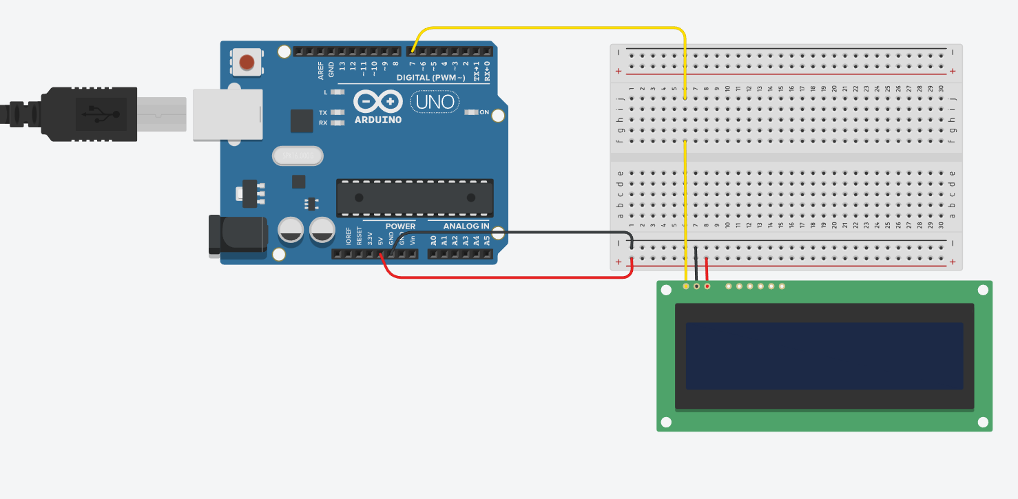
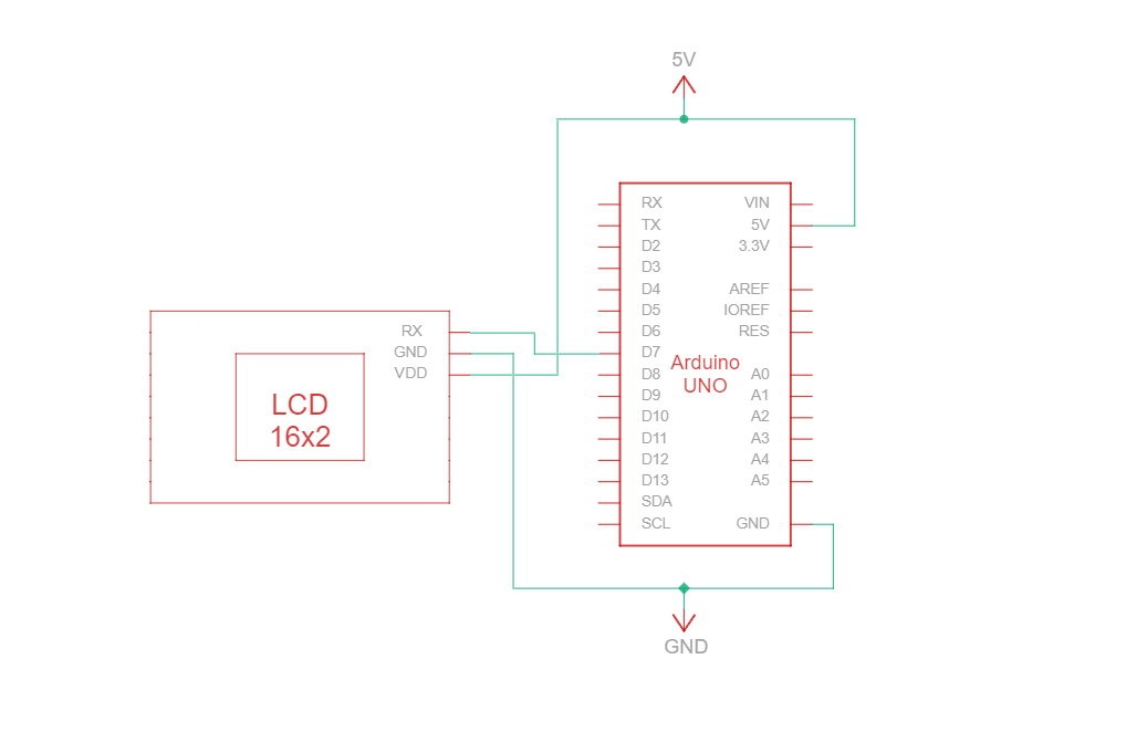
O RS232 TTL é um protocolo de comunicação em série que utiliza as especificações do tipo RS232, mas com níveis lógicos TTL (0 V a Vcc, normalmente 3,3 V ou 5 V). O circuito de ligação RS232 TTL entre o Arduino e o visor Newhaven de 16 caracteres utiliza apenas três fios:
| Arduino | LCD | Tipo de ligação |
|---|---|---|
| Pino de 5 V | Pino 3: V DD | Potência |
| Pino de terra | Pino 2: Terra | Terreno |
| Pino 7: Pino de E/S digital | Pino 1: RX | Porta de entrada série RS-232 (TTL) |
Nota:
Os terminais R1 e R2 no visor têm de estar abertos para ativar o modo RS232 TTL, conforme especificado na ficha técnica.
Circuito de ligação RS232 TTL
Esquema de ligações RS232 TTL
Criámos um tutorial detalhado e acessível a principiantes no Instructables sobre a comunicação RS232 TTL. O tutorial inclui todos os passos necessários para concluir este projeto. Confira-o aqui: www.instructables.com/Arduino-LCD-Tutorial/
Arduino - «Hello World!» no ecrã LCD! Exemplo de código utilizando comunicação série RS232 TTL
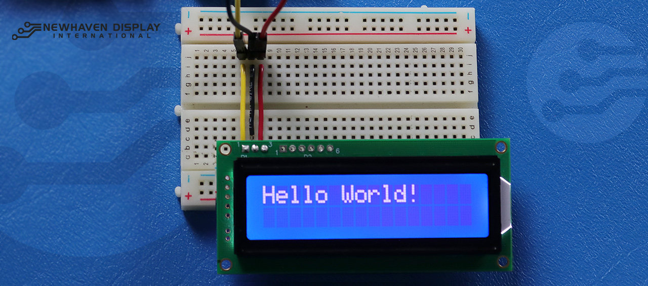
O exemplo de código seguinte apresenta «Hello Word!» no ecrã LCD através de comunicação RS232 TTL.
/***************************************************** Este código foi escrito para o Arduino UNO utilizando a interface RS-232. /* Referência de ligação RS-232 para: NHD-0216K3Z-NSW-BBW-V3 --------------------------- LCD | Arduino --------------------------- 1(RX) --> 7 2(VSS) --> Terra 3(VDD) --> 5 V */ #define P1 7 //RX: o pino no qual se recebem os dados seriais. /***************************************************** Configuração RS-232 para comandos e dados. Para mais informações sobre RS-232, visite o nosso Centro de Apoio /*****************************************************/ #include#define RxPin P1 SoftwareSerial NHD_LCD = SoftwareSerial(P1, RxPin); /***************************************************** Set LCD Contrast /*****************************************************/ void Set_Contrast() { NHD_LCD.write(0xFE); //Prefix command NHD_LCD.write(0x52); //Contrast command NHD_LCD.write(0x28); //Set contrast value delayMicroseconds(500); } /***************************************************** Clear LCD /*****************************************************/ void Clear_display() { NHD_LCD.write(0xFE); //Prefix command NHD_LCD.write(0x51); //Clear Display delayMicroseconds(1500); } /***************************************************** Set Arduino UNO IO ports as Output mode /*****************************************************/ void Set_Pins() { pinMode(RxPin, OUTPUT); } /***************************************************** Set LCD Backlight /*****************************************************/ void Set_Backlight() { NHD_LCD.write(0xFE); //prefix command NHD_LCD.write(0x53); //Backlight command NHD_LCD.write(0x08); //Set backlight value delayMicroseconds(100); } /***************************************************** Set cursor Mode = 0 sets Blinking cursor off Mode = 1 sets Blinking cursor on /*****************************************************/ void Set_Cursor(int mode) { NHD_LCD.write(0xFE); //Prefix command if (mode == 0) { NHD_LCD.write(0x4c); //Turn blinking cursor off } else if (mode == 1) { NHD_LCD.write(0x4b); //Turn blinking cursor on } delayMicroseconds(100); } /***************************************************** Write "Hello World!" to LCD /*****************************************************/ void Hello_World() { NHD_LCD.write(0x48); // H NHD_LCD.write(0x65); // e NHD_LCD.write(0x6C); // l NHD_LCD.write(0x6C); // l NHD_LCD.write(0x6F); // o NHD_LCD.write(0x11); // Blank NHD_LCD.write(0x57); // W NHD_LCD.write(0x6f); // o NHD_LCD.write(0x72); // r NHD_LCD.write(0x6c); // l NHD_LCD.write(0x64); // d NHD_LCD.write(0x21); // ! } /***************************************************** Main function /*****************************************************/ void setup() { NHD_LCD.begin(9600); //Sets 9600 Baud Rate the display can receive and transmit data at a rate of 9600 bits per second by default. delay(15); Set_Pins(); //Set IO ports Set_Cursor(0); //Turns off blinking cursor Set_Contrast(); //Set display Contrast Set_Backlight(); //Set display Backlight Clear_display(); //Clear display Hello_World(); //Display "Hello Wolrd!" } void loop() { }
Resolução de problemas do seu LCD - Projeto Arduino
A seguir, iremos abordar alguns passos comuns a seguir quando surgirem dificuldades ou problemas com o seu projeto Arduino - LCD.
- Verifique as ligações dos fios: O problema mais comum ao ligar um ecrã LCD a um Arduino é uma ligação incorreta dos fios. Verifique as ligações elétricas comparando-as com o diagrama de pinos e o esquema de circuitos fornecidos, para garantir uma ligação correta. Além disso, tenha em atenção que o NHD-0216K3Z-NSW-BBW-V3 pode ser configurado para funcionar com as interfaces SPI, I2C e RS232 TTL. É necessário soldar um resistor de 0 ohms na secção R2 da placa de circuito impresso para que funcione com a interface SPI.
- Inspecione os componentes: verifique se há sinais visíveis de danos no Arduino, no ecrã LCD ou nos fios de ligação.
- Verifique o código: Certifique-se de que o código carregado no seu Arduino está correto e não contém erros.
- Verifique a fonte de alimentação: certifique-se de que a fonte de alimentação é suficiente para alimentar tanto o Arduino como o ecrã LCD.
- Teste com um ecrã LCD que se saiba que funciona bem: Se continuar a ter problemas, tente ligar um ecrã LCD diferente, que se saiba que funciona bem, ao seu Arduino. Isto irá ajudá-lo a determinar se o problema está no ecrã LCD ou na própria placa Arduino.
- Ajustar o contraste: Se tiver dificuldade em ver o texto apresentado no ecrã LCD, tente ajustar o contraste através da função do software
Set_Contrast(), tal como descrito acima. Condições de iluminação diferentes podem exigir definições de contraste diferentes para uma visibilidade ideal. - Verifique a versão do IDE do Arduino: Certifique-se de que está a utilizar a versão mais recente do IDE do Arduino. As versões desatualizadas podem conter erros ou ser incompatíveis com o seu projeto.
- Teste funcionalidades individuais: Se estiver a ter problemas com funcionalidades específicas, como a deslocamento ou o controlo do contraste, experimente executar um código mais simples, como o exemplo «Hello World!», para isolar o problema. Isto pode ajudá-lo a determinar se o problema está relacionado com o código ou com o hardware.
- Procure ajuda na comunidade: Se não conseguir resolver o problema depois de seguir os passos de resolução de problemas acima, considere procurar ajuda na comunidade online. Fóruns online, como o Fórum de Suporte da Newhaven Display, oArduino Stack Exchange ou o fórumArduino.cc, são excelentes recursos para obter ajuda de utilizadores experientes.
Ao seguir estes passos de resolução de problemas, deverá conseguir diagnosticar e resolver a maioria dos problemas relacionados com a ligação de um ecrã LCD a uma placa Arduino. Lembre-se de que a paciência e a atenção aos detalhes são fundamentais na resolução de problemas em projetos de eletrónica.
Recursos adicionais
- Site oficial do Arduino UNO.
- Descrição do produto LCD 16x2.
- Ficha técnica e especificações do produto LCD 16x2.
- Tutorial do Instructables sobre Arduino e LCD, ideal para principiantes
- Fórum de apoio para ecrãs LCD de caracteres.
- Leia o nosso guia para principiantes sobre a prototipagem de ecrãs.
- Código de exemplo para um ecrã LCD de caracteres.
- Saiba como proteger os equipamentos eletrónicos contra descargas eletrostáticas (ESD).
- Saiba mais sobre os tipos de ecrãs LCD.
- Saiba mais sobre os modos do ecrã LCD.