How to Display Images on a TFT LCD
Apr 2nd 2024
TFT LCDs, or thin-film transistor liquid-crystal displays, are a type of LCD commonly used in various devices, including smartphones, tablets, and TVs. TFT LCDs are known for their high image quality, fast response times, and low power consumption.
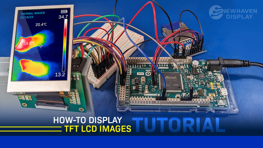
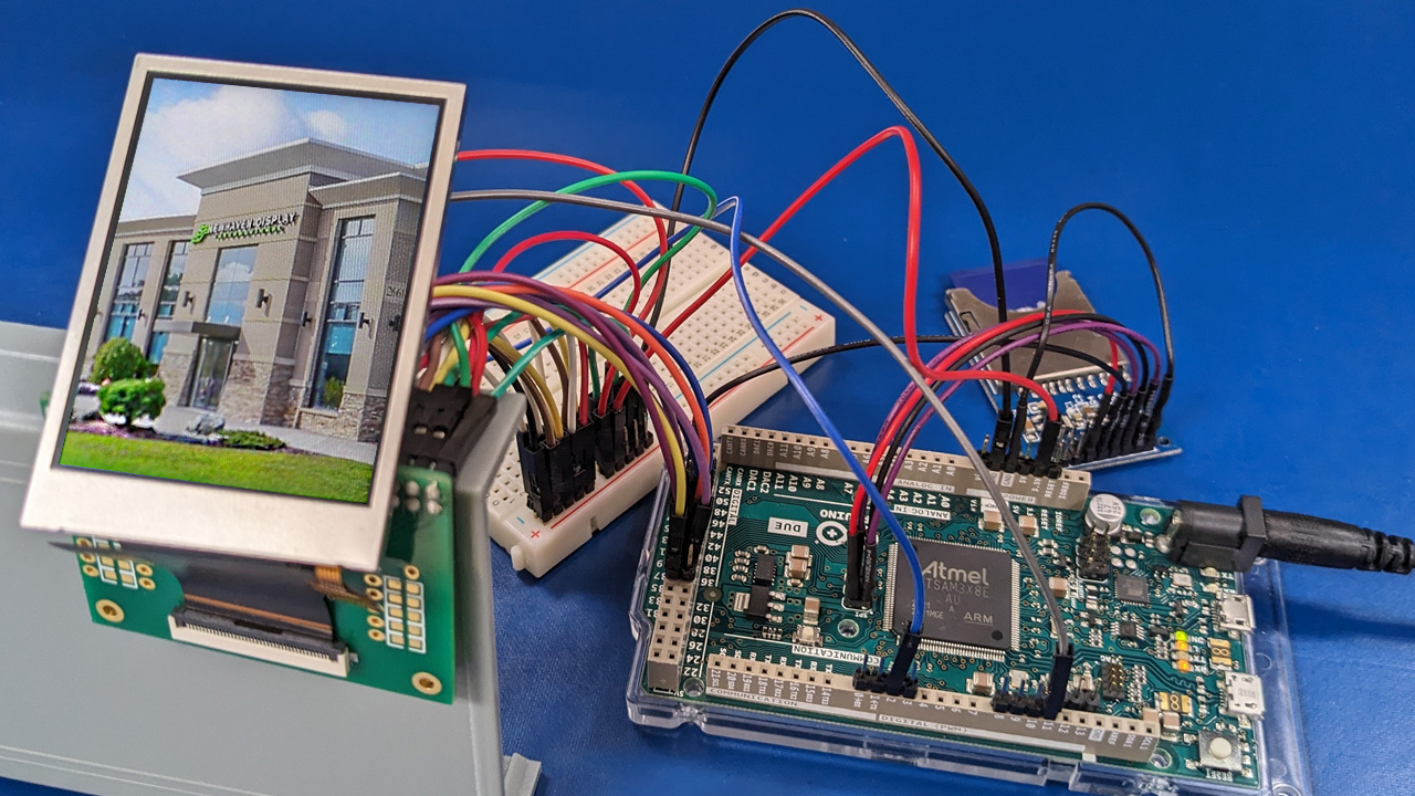
One of the most commonly used applications of TFT LCDs is displaying images. This makes them ideal for various projects, such as digital photo frames, digital signage, and DIY projects. In this article, we will show you how to display images on a TFT LCD using an SD card and the Arduino Due.
In this article:
Things You Will Need
- Arduino Due Microcontroller Board
- 240x320 TFT with ST7789VI or equivalent IC (NHD-2.4-240320AF-CSXP)
- A 40-pin 0.5mm pitch FFC breakout board (NHD-FFC40)
- An SD card
- An SD card breakout board
- A breadboard
- Jumper wires
- A USB cable for the microcontroller
- Arduino IDE software
- LCD Image Converter software
Pinout Table
Complete pinout description and connections for the connection between the TFT LCD, SD card breakout board, and the Arduino Due.
TFT LCD and Arduino Due Pinout
| LCD Pin | Symbol | Connection |
|---|---|---|
| 1 | GND | GND |
| 2 | NC | NC |
| 3 | NC | NC |
| 4 | NC | NC |
| 5 | NC | NC |
| 6 | SDO | NC |
| 7 | VDD | 3.3V |
| 8 | VDDI | 3.3V |
| 9 | SDA | NC |
| 10 | CSX | GND |
| 11 | DCX | Arduino Pin 2 |
| 12 | WRX | Arduino Pin 11 |
| 13 | RDX | 3.3V |
| 14 | DB0 | NC |
| 15 | DB1 | NC |
| 16 | DB2 | NC |
| 17 | DB3 | NC |
| 18 | DB4 | NC |
| 19 | DB5 | NC |
| 20 | DB6 | NC |
| 21 | DB7 | NC |
| 22 | DB8 | Arduino Pin 33 |
| 23 | DB9 | Arduino Pin 34 |
| 24 | DB10 | Arduino Pin 35 |
| 25 | DB11 | Arduino Pin 36 |
| 26 | DB12 | Arduino Pin 37 |
| 27 | DB13 | Arduino Pin 38 |
| 28 | DB14 | Arduino Pin 39 |
| 29 | DB15 | Arduino Pin 40 |
| 30 | RESX | 3.3V |
| 31 | IM0 | 3.3V |
| 32 | IM2 | GND |
| 33 | GND | GND |
| 34 | LED-K1 | GND |
| 35 | LED-K2 | GND |
| 36 | LED-K3 | GND |
| 37 | LED-K4 | GND |
| 38 | LED-A | 3.3V |
| 39 | GND | GND |
| 40 | TE | NC |
SD Card Breakout Board Pinout:
| SD Breakout Pin | Connection |
|---|---|
| GND | Arduino Due SPI Pin 6 |
| MISO | Arduino Due SPI Pin 1 |
| SCK | Arduino Due SPI Pin 3 |
| MOSI | Arduino Due SPI Pin 4 |
| CS | Arduino Due Pin 49 |
| 5V | Arduino Due SPI Pin 2 |
| 3.3V | NC |
Wiring Diagram
The wiring diagram below shows how to connect the TFT LCD and SD card to the Arduino Due for displaying graphics and accessing the SD card.
 Click to expand
Convert Image to Text File & Save to SD Card
Most LCDs do not directly interpret standard image formats like JPEG or PNG. Instead, they use raw pixel data, often represented in hexadecimal format. We first need to convert the image to an image data array by downloading the LCD Image Converter software and following these steps:
- Open LCD Image Converter software.
- Go to Image -> Import and open the image you want to display on the LCD. Image file resolution must match the resolution of the LCD.
- Go to Options -> Conversion and ensure the “Color R5G6B5” preset is selected.
- Click on the “Image” tab. In the “Common” section, uncheck “Split to rows” and set block size to "8-bit."
- At the bottom-left of the window, click “Show Preview.”
- Copy and paste the hex values into a text editor and save the file as “image1.txt.”
- Transfer the text file to an SD card and insert the SD card into the breakout board.
Copy Example Code to Arduino IDE
Open the Arduino IDE and start a new Sketch. Clear any pre-existing code, then copy and paste the code provided below.
/* /Newhaven Display invests time and resources providing this open source code, /Please support Newhaven Display by purchasing products from Newhaven Display! * * This code is provided as an example only and without any warranty by Newhaven Display. * Newhaven Display accepts no responsibility for any issues resulting from its use. * The developer on the final application incorporating any parts of this * sample code is responsible for ensuring its safe and correct operation * and for any consequences resulting from its use. * See the GNU General Public License for more details. */ #include#include #include /**************************************************** * PINOUT: Arduino Due -> 2.4" TFT * *****************************************************/ #define RS 2 #define WR 11 const char slave = 0x38; const int ChipSelect = 49; int image_value = 0; File myFile; /**************************************************** * Function Commands * ******************************************************/ void comm_out(unsigned char c) { PIOB -> PIO_CODR = 1 << 25; //RS LOW REG_PIOC_ODSR = c << 1; PIOD -> PIO_CODR = 1 << 7; //WR LOW PIOD -> PIO_SODR = 1 << 7; //WR HIGH } void data_out(unsigned char d) { PIOB -> PIO_SODR = 1 << 25; //RS HIGH REG_PIOC_ODSR = d << 1; PIOD -> PIO_CODR = 1 << 7; //WR LOW PIOD -> PIO_SODR = 1 << 7; //WR HIGH } //-=-=-=-=-=-=-=-=-=-=-=-=-=-=-=-=-=-=-=-=-=-=-=-=-=-=-=-=-=-=-=-=-=-=-= // Window Set Function //-=-=-=-=-=-=-=-=-=-=-=-=-=-=-=-=-=-=-=-=-=-=-=-=-=-=-=-=-=-=-=-=-=-=-= void window_set(unsigned s_x, unsigned e_x, unsigned s_y, unsigned e_y) { comm_out(0x2a); //SET column address data_out((s_x)>>8); //SET start column address data_out(s_x); data_out((e_x)>>8); //SET end column address data_out(e_x); comm_out(0x2b); //SET page address data_out((s_y)>>8); //SET start page address data_out(s_y); data_out((e_y)>>8); //SET end page address data_out(e_y); } /**************************************************** * Initialization and Setup Routine * *****************************************************/ void setup() { delay(100); pinMode(RS,OUTPUT); pinMode(WR,OUTPUT); PIOC->PIO_OER = 0xFFFFFFFF; digitalWrite(WR, LOW); comm_out(0x28); //display off comm_out(0x11); //exit SLEEP mode delay(100); comm_out(0x36); //MADCTL: memory data access control data_out(0x10); //changing from 0x88 comm_out(0x21); //display inversion comm_out(0x3A); //COLMOD: Interface Pixel format *** 65K-colors in 16bit/pixel (5-6-5) format when using 16-bit interface to allow 1-byte per pixel data_out(0x55); //0x55 = 65k //0x65 = 262k comm_out(0xB2); //PORCTRK: Porch setting data_out(0x0C); data_out(0x0C); data_out(0x00); data_out(0x33); data_out(0x33); comm_out(0xB7); //GCTRL: Gate Control data_out(0x35); comm_out(0xBB); //VCOMS: VCOM setting data_out(0x2B); comm_out(0xC0); //LCMCTRL: LCM Control data_out(0x2C); comm_out(0xC2); //VDVVRHEN: VDV and VRH Command Enable data_out(0x01); data_out(0xFF); comm_out(0xC3); //VRHS: VRH Set data_out(0x11); comm_out(0xC4); //VDVS: VDV Set data_out(0x20); comm_out(0xC6); //FRCTRL2: Frame Rate control in normal mode data_out(0x0F); comm_out(0xD0); //PWCTRL1: Power Control 1 data_out(0xA4); data_out(0xA1); comm_out(0xE0); //PVGAMCTRL: Positive Voltage Gamma control data_out(0xD0); data_out(0x00); data_out(0x05); data_out(0x0E); data_out(0x15); data_out(0x0D); data_out(0x37); data_out(0x43); data_out(0x47); data_out(0x09); data_out(0x15); data_out(0x12); data_out(0x16); data_out(0x19); comm_out(0xE1); //NVGAMCTRL: Negative Voltage Gamma control data_out(0xD0); data_out(0x00); data_out(0x05); data_out(0x0D); data_out(0x0C); data_out(0x06); data_out(0x2D); data_out(0x44); data_out(0x40); data_out(0x0E); data_out(0x1C); data_out(0x18); data_out(0x16); data_out(0x19); comm_out(0x2A); //X address set data_out(0x00); data_out(0x00); data_out(0x00); data_out(0xEF); comm_out(0x2B); //Y address set data_out(0x00); data_out(0x00); data_out(0x01); data_out(0x3F); delay(10); comm_out(0x29); //display ON delay(10); SD.begin(ChipSelect); } /***************************************************** * Loop Function, to run repeatedly * *****************************************************/ void loop() { SD_Card_Image(1); delay(5000); //SD_Card_Image(2); //delay(5000); //SD_Card_Image(3); //delay(5000); //SD_Card_Image(4); //delay(5000); //SD_Card_Image(5); //delay(5000); } void SD_Card_Image(unsigned char image){ /*The images used are in a textfile*/ unsigned char dummy; unsigned int incr =0; switch (image){ case 1: image_value=1; myFile = SD.open("image1.txt"); break; case 2: image_value=2; myFile =SD.open("image2.txt"); break; case 3: image_value=3; myFile = SD.open("image3.txt"); break; case 4: image_value=4; myFile = SD.open("image4.txt"); break; case 5: image_value=5; myFile = SD.open("image5.txt"); break; } comm_out(0x2A); /*X address set*/ data_out(0x00); data_out(0x00); data_out(0x00); data_out(0xEF); comm_out(0x2B); /*Y address set*/ data_out(0x00); data_out(0x00); data_out(0x01); data_out(0x3F); comm_out(0x2C); /*command to begin writing to frame memory */ byte data_in1,data_in2,data_in,data_out_value; uint8_t data_send; char data_conv[1]={0}; int i; int track ; while (myFile.available()){ /*convert the input char data to integers*/ dummy = myFile.read(); dummy = myFile.read(); data_in1 = myFile.read(); data_in2 = myFile.read(); data_in=data_in1; if(data_in >=48 && data_in<=57){ /*if values are in range of 0-9 values*/ data_in1 = data_in-48; track=1; } if(data_in <=102 && data_in>=97){ /*if values are in range of a-f*/ data_in1 = data_in - 87; track=1; } if( data_in ==32/*Space*/ || data_in==44 /*comma*/ || data_in == 120 /*x*/){ dummy =data_in; track=0; data_in1 =0; data_in2 =0; } data_in=data_in2; if(data_in >=48 && data_in<=57){ /*if values are in range of 0-9 values*/ data_in2 = data_in-48; track=1; } if(data_in <=102 && data_in>=97){/*if values are in range of a-f*/ data_in2 = data_in - 87; track=1; } if( data_in ==32/*Space*/ || data_in==44 /*comma*/ || data_in == 120 /*x*/){/*skip dummy data*/ dummy =data_in; track=0; data_in1 =0; data_in2 =0; } dummy = myFile.read(); dummy = myFile.read(); data_out_value = data_in1<<4 | data_in2; data_out(data_out_value); } myFile.close(); }
Upload the Code to Arduino
The final step is to upload the code to the Arduino IDE.
- Connect the Arduino to your PC with the USB-B cable.
- In the Arduino IDE, select the board and port.
- Click the “Upload” button to program the Arduino with your code.
Once the code is successfully uploaded, your image should appear on the LCD screen.
Learn More
For more tutorials and insights, check out our other posts:
Conclusion
Whether you are learning, prototyping, or want to have fun playing around with electronics, this tutorial outlines the basics of reading hex image data from an SD card and displaying it on a TFT LCD. This is only a starting point, and the possibilities for expansion are endless. We really hope you enjoyed this tutorial!