
How to Display a Custom Image on a Graphic LCD
Sep 28th 2023
Graphic LCD displays can be used to display a variety of information, including text, images, and graphs. This article will walk you through the steps to display custom images on a graphic LCD. We will start by creating the graphic in a graphics editor. Once the graphic is created, we must convert it into a format that the LCD display can understand. We can do this using a tool such as the LCD Assistant. Finally, we will write some code to display the graphic on the LCD display.
This tutorial will be using an Arduino Uno, but the principles can be applied to any microcontroller with a graphic LCD display.
Table of Contents
Hardware and Tools
- Arduino UNO
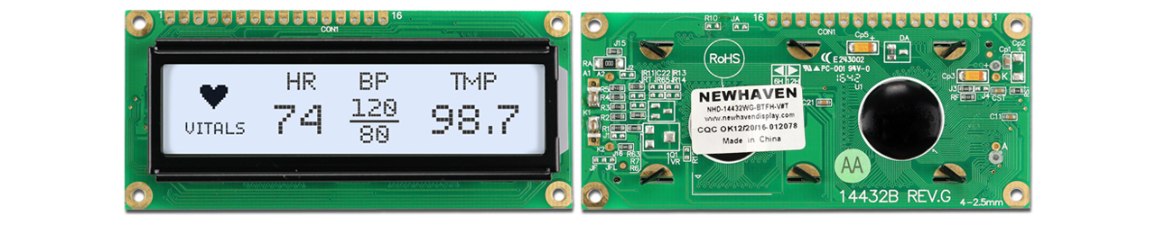
- Graphic LCD: NHD-14432WG-BTFH-V#T
- Single row pin header connector
- Breadboard
- Jumper wires
- Solder and soldering iron
- USB A male to B Male Cable (printer cable)
- Arduino IDE
- Image editing software such as MS Paint and GIMP (optional)
- LCD Assistant software to convert monochromatic bitmap images to image data arrays (optional)
Graphic LCD Pinout (Parallel Interface)
The Newhaven display NHD-14432WG-BTFH-V#T is a 144x32 pixel graphic LCD module with the ST7920 controller. It uses parallel communication and operates at a supply voltage of 5V.
This 16-pin character LCD is available with or without a pre-soldered 16-pin header and can be purchased here. The display datasheet can be viewed or downloaded here.
| LCD Pin | Symbol | Connection |
|---|---|---|
| 1 | V SS | Arduino: GND |
| 2 | V DD | Arduino: 5V |
| 3 | V O | No Connect |
| 4 | RS | Arduino: D8 |
| 5 | R/W | Arduino: D9 |
| 6 | E | Arduino: D10 |
| 7 | DB0 | Arduino: D0 |
| 8 | DB1 | Arduino: D1 |
| 9 | DB2 | Arduino: D2 |
| 10 | DB3 | Arduino: D3 |
| 11 | DB4 | Arduino: D4 |
| 12 | DB5 | Arduino: D5 |
| 13 | DB6 | Arduino: D6 |
| 14 | DB7 | Arduino: D7 |
| 15 | A | 5V with 30Ω in series |
| 16 | K | Power Supply: GND |
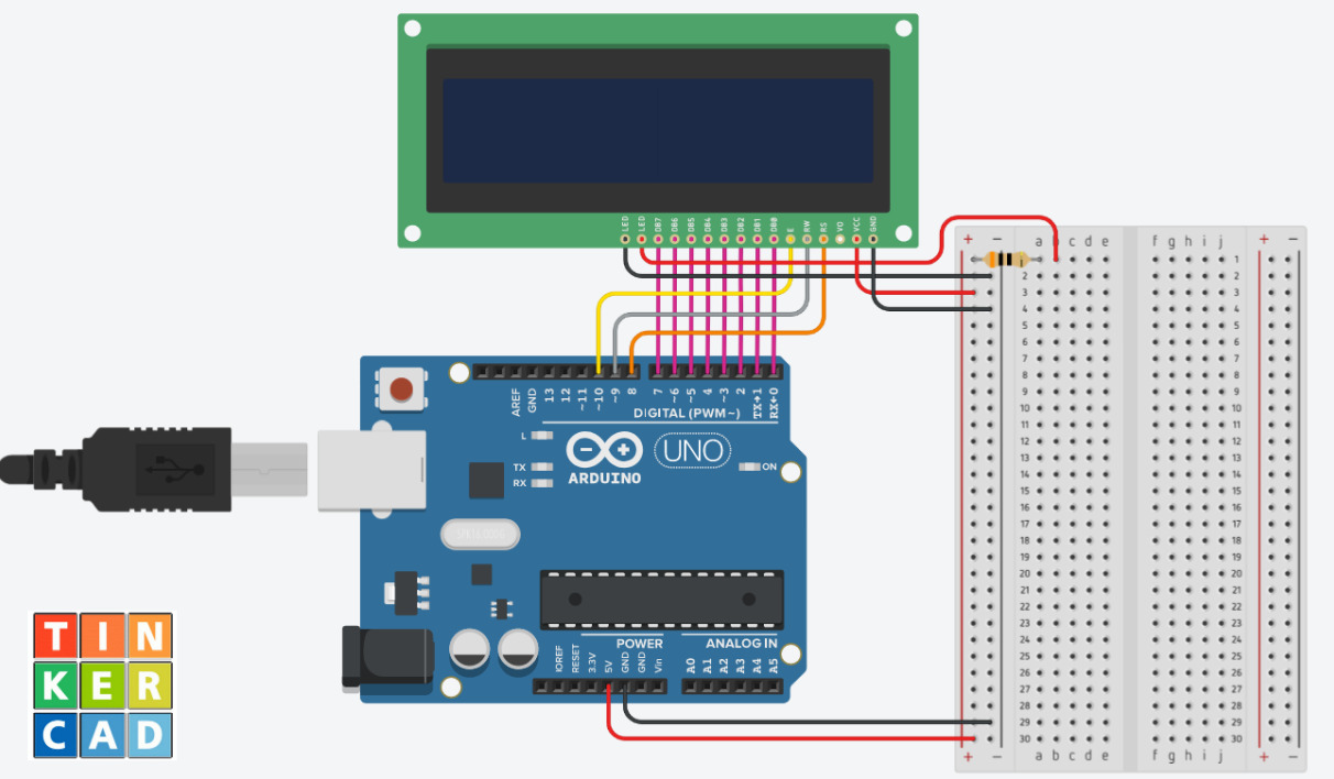
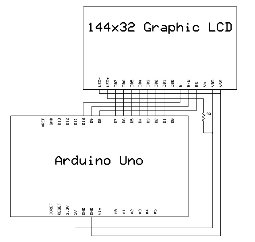
Circuit - Connection Diagram and Schematic
Connection diagram
Schematic
Create a Custom Graphic
To display a custom or pre-existing image on a graphic LCD, the image needs to be converted into a format compatible with the LCD, often in the form of a data array. Various graphic design tools, such as Microsoft Paint, GIMP, and Photoshop, can help with this task. However, for the scope of this tutorial, we will focus on using Microsoft Paint.
If you don't want to create a custom image or want a faster way, you can skip the image creation and convertion steps and use the pre-generated image data array code here.
How to create a custom image for a graphic LCD
- Open a new file in Microsoft Paint.
- Go to File -> Properties.
- Set the following properties:
- Units: Pixels
- Colors: Black and White
- Width: Number of pixels wide of your display (144 in our example)
- Height: Number of pixels high of your display (32 in our example)
- Go to the “View” tab and check “Gridlines.”
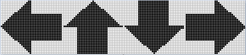
- Use the tools to create a custom graphic.
- 6. Go to File -> Save as, create a file name for your graphic and select Save as type: Monochrome Bitmap (*.bmp;*.dib).
After processing the data array code generated by the LCD assistant software, remove the "const" keyword. Otherwise, the data array may not work properly.
In the image settings above, the color mode is set to monochrome for optimal compatibility and the image size of 144 x32 matches the LCD screen dimensions so the image fits perfectly in the screen.
If you use a Mac or prefer open-source image editing software, you can use GIMP by following similar document settings, export the image as X Bitmap image, and open it on any code editor to view the image data array. With GIMP, you can skip the step of converting the graphic to a data array. Additionally, the online tool Image2cpp can also be used for this purpose.
Convert the Graphic to a Data Array
Converting a graphic to a data array typically involves extracting the pixel color data from an image and representing it numerically in a data array. There are several methods and tools available for this conversion, such as programming libraries, custom software, and online tools. In this tutorial, we will be using the LCD Assistant software.
- Open the LCD Assistant software: Download Here.
- Set byte orientation to “Horizontal.”
- Go to File -> Load Image and select the BMP file for your graphic.
- Go to File -> Save Output and save the file name with a .h extension.
- Open the .h file to copy the data array.
Whether you choose LCD Assistant or GIMP, the goal is to get a numerical representation of your image similar to the example for this tutorial.
Add the Image Data Array to the Example Code
There are two primary methods to incorporate the image data array into your Arduino sketch: directly embedding the data within the sketch or using a separate header file. For this tutorial, we will use a separate file in the same project directory. Your project folder should have the .h image data array file and the .ino file with the Arduino example code below.
Copy Example Code to Arduino IDE
Open the Arduino IDE and start a new Sketch. Clear any pre-existing code, then copy and paste the code provided below.
     //---------------------------------------------------------
    /*
      Program for writing to NHD-14432WG-BTFH-V#T LCD with the ST7920 controller
      This code is written for the Arduino Uno R3 using 8-bit parallel interface
      Newhaven Display invests time and resources providing this open source code,
      Please support Newhaven Display by purchasing products from Newhaven Display!
      This code is provided as an example only and without any warranty by Newhaven Display.
      Newhaven Display accepts no responsibility for any issues resulting from its use.
      The developer of the final application incorporating any parts of this
      sample code is responsible for ensuring its safe and correct operation
      and for any consequences resulting from its use.
      See the GNU General Public License for more details.
      Use Horizontal Orientation when converting BMP to hex code
      to display custom image using LCD assistant.
    */
    //---------------------------------------------------------
    #define RS      8  //Register Select signal
    #define RW      9  //Read/Write signal
    #define E       10 //Enable signal
    #include "144_32_Arrows.h"
    /****************************************************
                      Function Commands
    *****************************************************/
    //--------------------------------------------------------------------------
    void command(unsigned char c){
      unsigned char i, temp;
      PORTD = c;
      digitalWrite(RS, LOW);               // Command
      digitalWrite(RW, LOW);               // Write
      digitalWrite(E, HIGH);
      delay(1);
      digitalWrite(E, LOW);
      delay(1);
    }
    //--------------------------------------------------------------------------
    void data(unsigned char d){
      unsigned char i, temp;
      PORTD = d;
      digitalWrite(RS, HIGH);              // Data
      digitalWrite(RW, LOW);               // Write
      digitalWrite(E, HIGH);
      delay(1);
      digitalWrite(E, LOW);
      delay(1);
    }
    /****************************************************
                      Display Commands
    *****************************************************/
    void disp(unsigned char *LCD_String)
    {
      unsigned int x, y, page;
      page = 0x80;
      for(int i=0;i<32;i++)
      {
        command(0x3E);
        command(page);
        command(0x80);
        for (x=0;x<18;x++){
          data(*LCD_String);
          LCD_String++;
        }
        page++;
      }
    }
    void Fill()
    {
      unsigned int x, y, page;
      page = 0x80;
      for (page=0x80;page<0xA1;page++)
      {
        command(0x3E);
        command(page);
        command(0x80);
        for (x=0;x<18;x++)
        {
          data(0xFF);
          delayMicroseconds(50);
        }
      }
    }
    void Clear()
    {
      unsigned int x, y, page;
      page = 0x80;
      for (page=0x80;page<0xA1;page++)
      {
        command(0x3E);
        command(page);
        command(0x80);
        for (x=0;x<18;x++)
        {
          data(0x00);
          delayMicroseconds(100);
        }
      }
    }
    /****************************************************
                Initialization For controller
    *****************************************************/
    void Initialization_Sequence()
    {
      command(0x38);        //Function Set: 8-bit mode, basic instruction
      delay(2);
      command(0x0C);        //Display control: Display on, cursor off, blink off
      delay(2);
      command(0x06);        //Entry Mode Set
      delay(2);
      command(0x02);        //Return home
      delay(100);
      command(0x01);        //Display Clear
      delay(10);
      for(int i=1;i<=32;i++){
        command(0x3E);
        command(0x80);
        command(0x80);
        for(int j=1;j<=40;j++){
          data(0x00);
        }
      }
    }
    /*****************************************************
                Setup Function, to run once
    *****************************************************/
    void setup() {
      DDRD = 0xFF; // First 8 pins of PORT D as output
      DDRB = 0x3F; // Port B first 6 pins as output
      Initialization_Sequence();
      delay(10);
      Fill();
      delay(500);
      Clear();
      delay(500);
    }
    /*****************************************************
                Loop Function, to run repeatedly
    *****************************************************/
    void loop() {
      disp(Arrows);
    }
Functions Overview:
- The command() function sends a command to the LCD.
- The data() function sends data to the LCD.
- The disp() function displays a 144x32 graphic on the LCD.
- The fill() function turns on all pixels of the LCD.
- The clear() function turns off all pixels of the LCD.
- The Initialization_Sequence() function sends the required instructions for initializing the LCD.
- The setup() function is the main function and is executed when the Arduino starts. The setup function calls the Initialization_Sequence() function, then turns on and off all the pixels on the LCD.
- The loop() function runs continuously after the setup() function is finished. The function calls the disp() function with the graphic data array as the argument.
Upload the Code to Arduino
- Connect the Arduino to your PC with the USB-B cable.
- In the Arduino IDE, select the board and port.
- Click the “Upload” button to program the Arduino with your code.
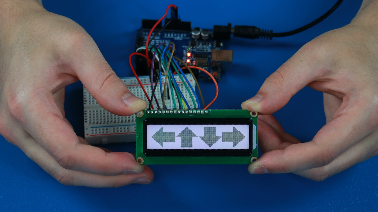
Once the code is successfully uploaded, your custom image should appear on the LCD screen.
Video Tutorial
Conclusion
Displaying custom images on a graphic LCD can enhance the user experience and provide a more interactive interface. By following the steps outlined in this article, from graphic creation to code implementation, users can seamlessly integrate custom graphics into their LCD displays. Whether you're using an Arduino Uno or another microcontroller, the principles remain consistent, ensuring a smooth process for all.