


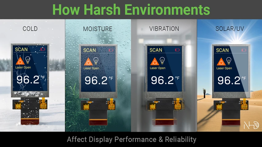
How Harsh Environments Affect Display Performance and Reliability
Nov 20th 2026
Harsh-environment performance is rarely determined by a single specification. Displays used in industrial, transportation, marine, outdoor, and other demanding applications can face temperature swings, moisture, vibration, mechanical shock, and solar exposure throughout their service life. Each condition affects different materials and components inside the display assembly, and the effects can intensify when several occur during the same operating cycle.
Reliable display design therefore depends on understanding the complete environmental profile. Exposure duration, repetition, sequencing, and interaction between stressors can reveal risks that individual maximum ratings may not capture.
What Makes an Environment Harsh for a Display?
A harsh environment is defined by the intensity, duration, repetition, and combination of stresses a display experiences across its service life. Temperature swings, moisture, vibration, mechanical shock, and solar exposure each affect materials differently, and repeated exposure can introduce failure mechanisms that may not appear during a short laboratory test.
Environmental sequencing also matters. Thermal cycling can move moisture through an enclosure, cold can reduce the flexibility of certain adhesives, and solar loading can raise internal temperatures while ultraviolet (UV) radiation degrades optical materials. Mechanical stress can then act on joints, mounts, or bonded layers already affected by those conditions.
Field failures often develop from a specific combination of events rather than one isolated extreme. Reproducing the original exposure profile becomes important during investigation because changing the sequence, duration, or operating state can produce a different result.
A meaningful harsh-environment specification needs to reflect actual use conditions across transport, storage, operation, and expected service life. The goal is to define the environment the display will experience, not simply collect a series of maximum ratings.
Extreme Temperatures Change Display Behavior
Temperature shifts alter the physical properties of materials throughout a display assembly. Liquid-crystal behavior, adhesives, polarizers, seals, connectors, and mounting structures can all respond differently at low and high temperatures. Repeated heating and cooling also introduce expansion and contraction across materials that do not move at the same rate.
How Cold Affects Response Time and Image Quality
Low temperatures increase liquid-crystal viscosity, slowing molecular movement and extending response time. Screen transitions may become sluggish, contrast can shift, and backlight characteristics may change near the lower end of the operating range.
Cold also changes the mechanical behavior of surrounding materials. Certain adhesives and polymers can become less flexible, increasing sensitivity to vibration, impact, or repeated movement. In rugged applications, low-temperature performance carries both optical and structural implications.
How Heat, Self-Heating, and Thermal Cycling Affect Displays
High temperatures can alter liquid-crystal performance, accelerate aging in optical materials, and place added stress on adhesives and bonded interfaces. Backlights and electronics also generate heat during operation, sometimes raising internal temperatures beyond the surrounding ambient conditions.
Thermal cycling creates another layer of stress. Repeated expansion and contraction can fatigue interfaces between glass, adhesives, connectors, and mounting structures over time. Different coefficients of thermal expansion across those materials can concentrate stress at connection points or bonded surfaces.
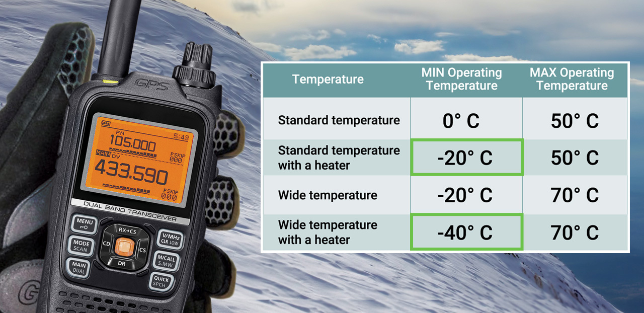
Integrated LCD heaters can support startup and response in severe cold, especially where low-temperature operation is a regular part of the application. Their use fits into a broader thermal strategy that accounts for startup conditions, operating duration, internal heat generation, and repeated temperature transitions.
Moisture and Condensation Can Cause Lasting Damage
Moisture-related failures often develop slowly. Condensation can form inside the display stack, fog optical paths, corrode indium tin oxide (ITO) traces and flex-circuit conductors, and promote electrochemical migration between conductive paths. Symptoms may appear well after the original exposure, making moisture one of the harder environmental risks to trace back to a single event.
Repeated temperature changes can make the problem worse. Air inside an enclosure expands during heating and contracts during cooling, moving humid air through seams and gaskets over time. Moisture can gradually reach areas that would remain dry during a short, steady-state humidity test.
Why Dew Point Matters More Than Humidity Alone
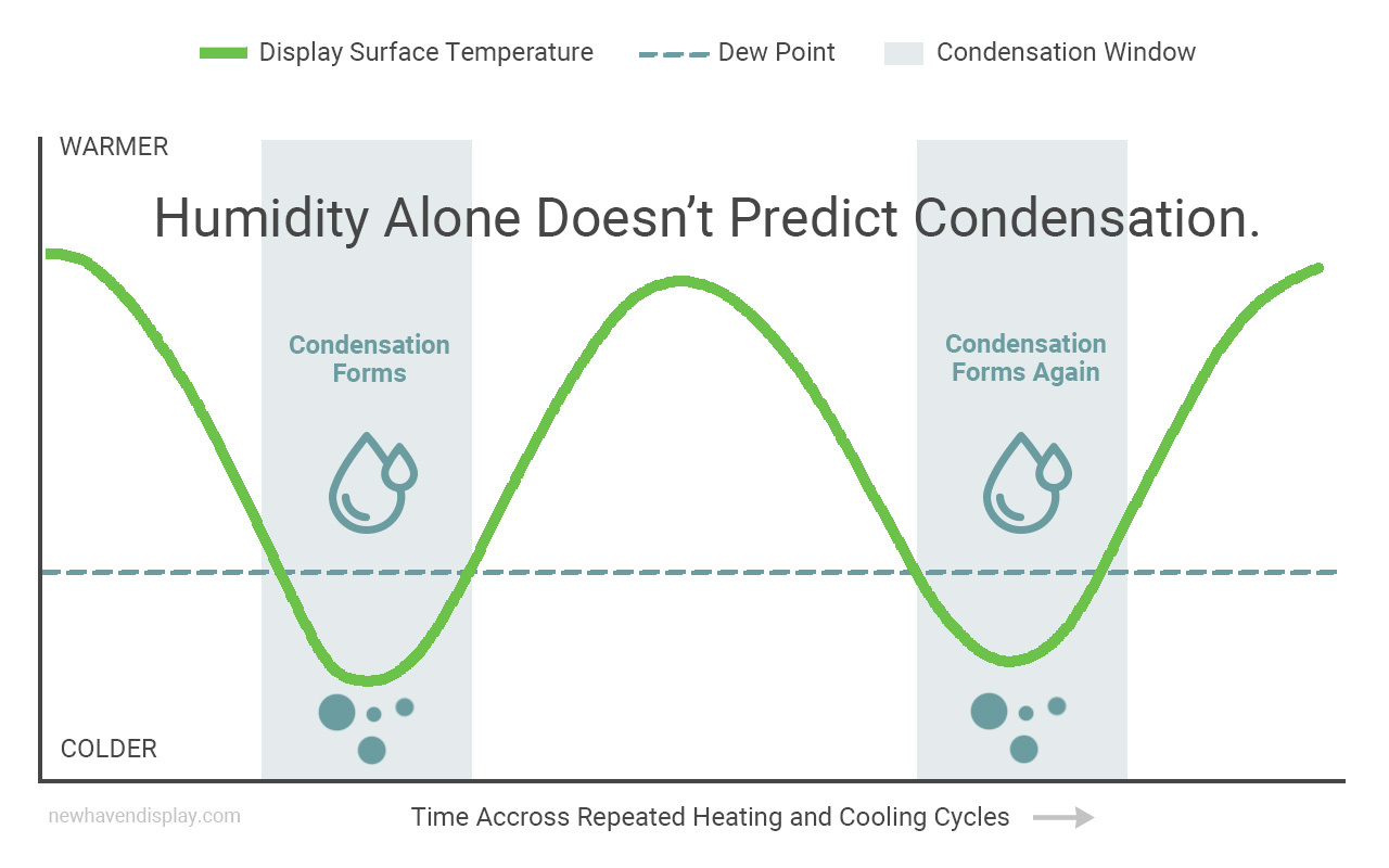
Relative humidity gives only part of the picture. Condensation begins when a surface temperature falls below the dew point, and water leaves the air as liquid. Inside a display assembly, that moisture can settle on glass, conductors, optical layers, or backlight components where removal is difficult or impossible during normal operation.
Dew-point crossings help explain why a display can pass a steady-humidity test yet still develop problems in service. A field environment may cycle through temperatures that repeatedly create condensation, even when the reported humidity level never appears extreme on its own. Internal glass staining, clouded backlight regions, corrosion, and intermittent electrical faults can all follow prolonged moisture exposure.
One common moisture-qualification condition is 85°C at 85% relative humidity, often referred to as 85/85. Steady-state damp heat testing can reveal one type of moisture risk, while cyclic humidity testing can expose problems tied to repeated condensation.
Why an IP Rating Does Not Tell the Whole Story
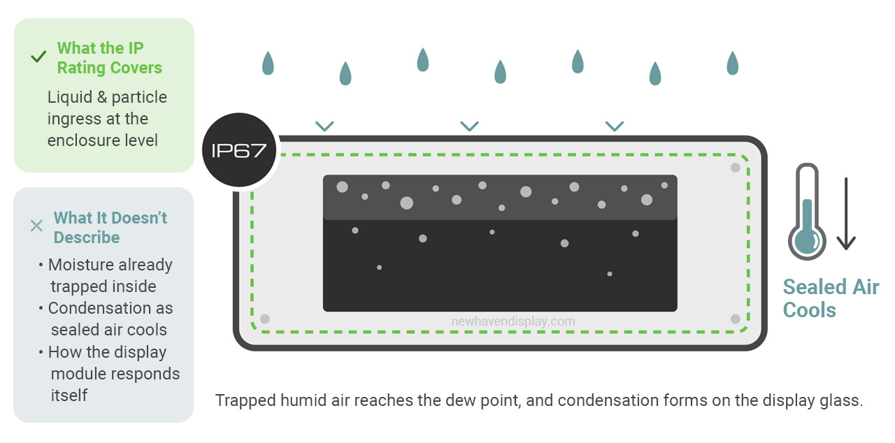
An ingress protection (IP) rating applies to the enclosure, not the display module mounted inside it. An IP67 enclosure, for example, addresses liquid and particle ingress at the enclosure level. It does not describe how the display responds to moisture already trapped inside or condensation created when sealed air cools.
Moisture performance needs separate consideration at the display level. Conformal coating, edge sealing, gasketing, vent membranes, desiccant, and low-level heating are among the design options that can reduce exposure or control condensation in harsh applications. The right combination depends on the enclosure, thermal cycle, electronics placement, and expected service conditions.
Vibration and Mechanical Shock Create Cumulative Stress
Vibration and shock place different kinds of mechanical stress on a display. Vibration creates fatigue through repeated motion over time, while shock comes from a single overload event such as a drop, hard landing, or sudden impact. Both can damage the display assembly, but they do not produce the same failure patterns or call for the same design response.
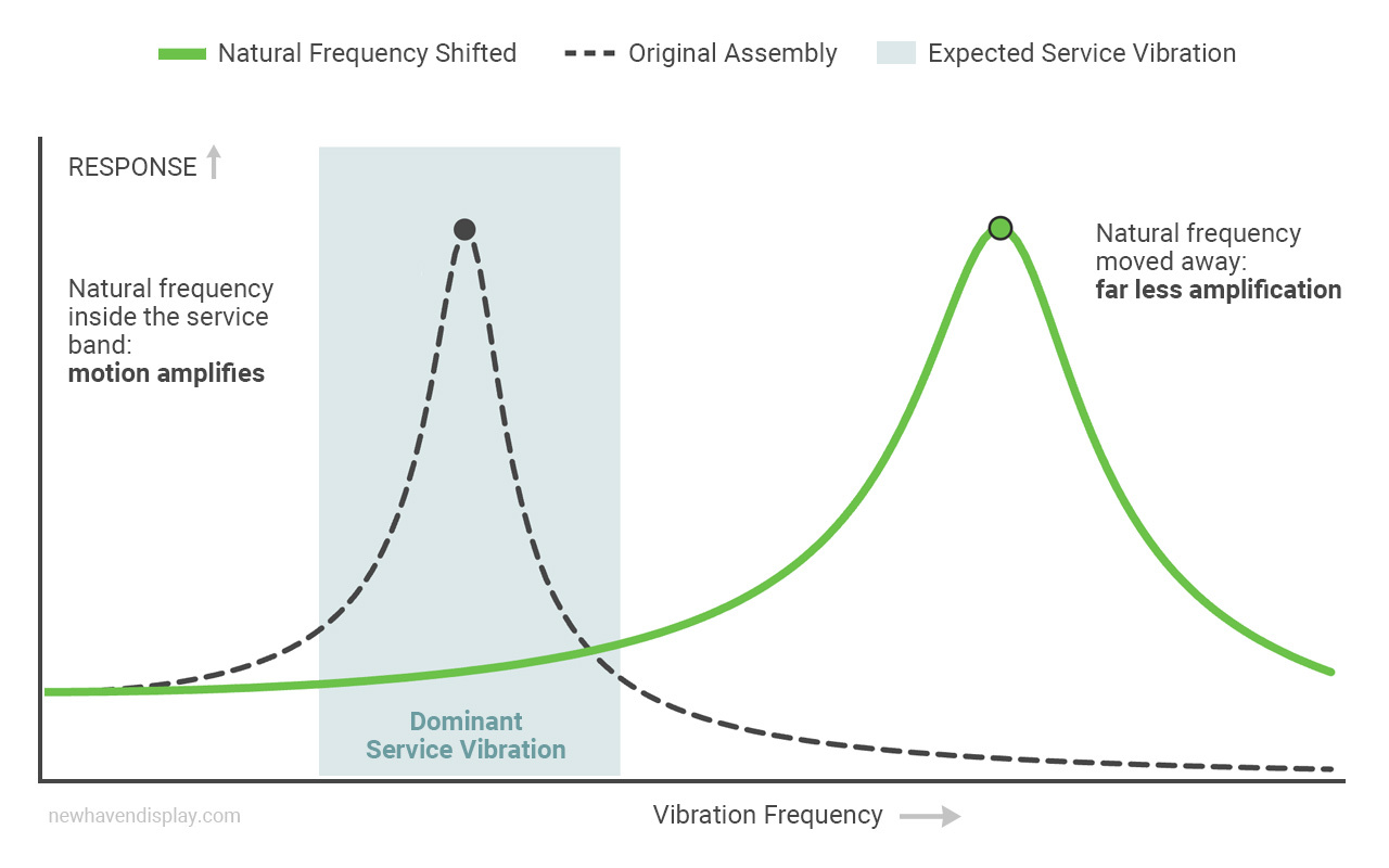
How Fatigue, Shock, and Resonance Affect Display Components
Repeated vibration can work at the weakest points in the assembly. Solder joints, flex cables, connectors, glass, bezels, and backlight assemblies are all susceptible to fatigue. Early signs may appear as intermittent faults, dead pixels, dark areas, or inconsistent responses before a complete failure develops.
Resonance adds another layer of risk. When vibration aligns closely enough to the assembly’s natural frequency, movement can increase well beyond the original input. A vibration level that seems manageable under one condition can become destructive when resonance is introduced. Harsh-environment mechanical design often focuses on moving the assembly’s natural frequencies away from the dominant vibration energy expected in service. Reducing overlap between those frequencies can limit the amplification that makes resonance so destructive.
Shock behaves differently. A sudden impact applies a short-duration load across the assembly and can expose weak points in glass support, mounting, cabling, and connection points. The same display can respond very differently to repeated vibration and to a single high-force event, so both conditions need separate consideration during qualification.
How Optical Bonding and Mounting Improve Mechanical Durability
Optical bonding can improve mechanical durability because it fills the air gap between the cover glass and the display panel. Once bonded, the layers share load more evenly and move as a more unified structure. That reduces independent glass flex, which can help limit cracking under vibration and shock.
Mounting strategy also affects how mechanical energy reaches the display. Compliant mounting and gasketing can help isolate the assembly from incoming vibration and reduce resonant peaks. Cable strain relief, support for heavier components, and careful printed circuit board layout can further reduce stress on solder joints and flex connections over time.
UV and Solar Exposure Degrade Display Materials
Ultraviolet (UV) exposure can cause gradual, irreversible changes across several display materials. In LCDs, polarizer films commonly use a stretched polyvinyl alcohol (PVA) layer doped with iodine to control light. UV radiation can degrade that chemistry, leading to yellowing, reduced polarization efficiency, washed-out contrast, and color shift. Adhesives, plastic housings, and gaskets can also experience yellowing, embrittlement, or surface breakdown after prolonged solar exposure.
How UV Exposure Affects Polarizers, Adhesives, and Readability
Outdoor readability depends heavily on the condition of the optical stack. UV-stabilized polarizers and UV-filtering cover materials can slow degradation, while UV-rated optically clear adhesives help preserve bond quality over longer exposure periods. High-brightness backlights, optical bonding, anti-glare treatments, and transflective designs can also support readability under strong ambient light.
Material selection directly influences long-term outdoor performance. Brightness alone does not protect polarizers, adhesives, or surrounding polymers from prolonged solar exposure.
Why Heat and UV Exposure Should Be Considered Together
Solar exposure raises temperature at the same time UV radiation reaches the display surface. Elevated heat can accelerate photochemical degradation in polarizers and adhesives, shortening the time it takes for visible aging to appear.
Outdoor qualification should account for surface temperature, exposure duration, enclosure design, material selection, and expected service life. Heat and UV exposure can accelerate aging in ways that isolated testing may not reveal.
Combined Environmental Stresses Can Multiply the Risk
Environmental stressors can alter one another’s effects on a display assembly. Moisture becomes more damaging when temperature cycling creates repeated condensation. Cold can reduce flexibility in adhesives before vibration reaches the assembly. Solar exposure can raise surface temperature while UV radiation accelerates material aging. The resulting failure may trace back to the interaction between conditions rather than any single rating.
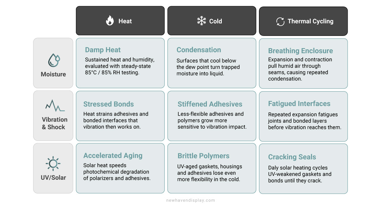
Why Real-World Conditions Are More Demanding Than Single-Variable Tests
Single-variable testing is useful for isolating a specific stress, but field conditions rarely remain isolated. A display installed outdoors may experience sunlight, heat, moisture, and temperature changes during the same day. A vehicle-mounted display may encounter vibration while internal materials are already affected by cold or heat.
Sequence can matter too. Moisture introduced during one phase may remain inside an enclosure until a later temperature drop creates condensation. Vibration can then act on materials already weakened through repeated thermal exposure. Recreating the same order of events can be necessary when investigating failures that do not appear under individual tests.
Specify an Environmental Profile, Not a List of Maximums
An environmental profile should identify operating and storage conditions, exposure duration, cycling frequency, and combinations likely to occur during service.
The highest individual value is not always the condition that creates the greatest risk. A moderate temperature paired with sustained UV exposure or recurring condensation may place greater stress on materials than a short excursion to a higher temperature. Real-use profiles give engineers a stronger basis for material selection and qualification planning.
How to Evaluate and Qualify Displays for Harsh Environments
Effective qualification begins at the assembled-product level. Cover glass, optical bonding, mounting hardware, cabling, connectors, and enclosure design can all change how environmental stress reaches the display. Testing the complete configuration can reveal interactions that may remain hidden during module-level evaluation.
Newhaven’s qualification work can include low-temperature storage down to −40°C and high-temperature storage up to +85°C. Powered operation may also be evaluated at −20°C, −40°C, +70°C, or +85°C, depending on the program. Applications exposed to rapid temperature change may call for thermal transitions spanning −40°C to +85°C.
Additional qualification can address high-temperature and high-humidity exposure, vibration, thermal shock, and electrostatic discharge. Each test targets a different failure path, giving engineers a clearer picture of how materials, connections, and the display assembly respond under harsh operating conditions.
Test selection should reflect the actual field environment identified early in development. A product exposed to recurring condensation needs a different qualification emphasis than equipment subjected to constant vibration or prolonged solar loading. Programs facing several stressors may also benefit from test sequences that recreate how those conditions occur during service.
Design Harsh Environment Displays for Long-Term Reliability
Newhaven’s harsh-environment engineering work spans industrial, medical, automotive, and consumer programs. That experience includes temperature extremes, humidity, thermal shock, vibration, electrostatic discharge, and combined environmental stress.
Our qualification process examines both powered operation and unpowered storage, including recovery after exposure. When a standard display configuration does not meet the application profile, our engineers can develop wide-temperature builds rated to −40°C to +85°C, integrate heater panels, add conformal coating for moisture protection, incorporate electromagnetic interference (EMI) mitigation, specify custom cover glass, or evaluate UV-resistant and chemical-resistant cabling.
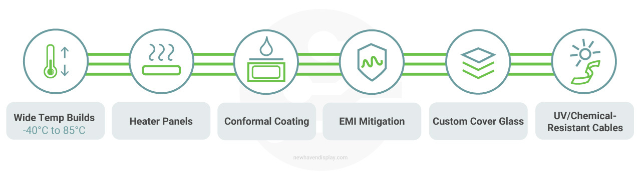
We evaluate the integrated stack, including cover glass, optical bonding, mounting, cabling, and enclosure design, to identify weak points before production and select modifications tied to the operating profile.
Our work is supported through an ISO 9001:2015 quality system and in-house engineering from initial display selection through custom development and qualification. Our process connects early environmental planning, display selection, targeted design changes, and qualification before production.
Talk to our engineering team about a harsh-environment display solution built around your application’s operating conditions.