


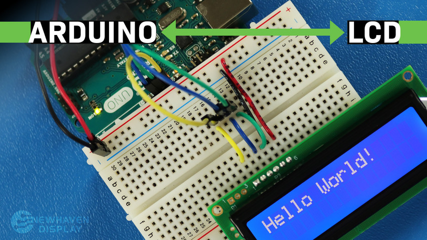
Cómo conectar LCD a Arduino
19 de mayo de 2023
La pantalla LCD (pantalla de cristal líquido) es una pantalla muy utilizada en proyectos con Arduino, ya que ofrece una forma sencilla de mostrar información al usuario, como texto y caracteres básicos. Es una pantalla útil tanto para principiantes como para usuarios experimentados y suele ser una de las primeras pantallas que se utilizan al empezar a trabajar con una placa Arduino.
En este tutorial te enseñaremos cómo conectar una pantalla LCD de caracteres de 16x2 a una placa Arduino UNO y cómo hacer que se comuniquen entre sí mediante comunicación serie.
Los principios que se explican en este tutorial se pueden aplicar también a otras pantallas LCD y a otras placas de desarrollo. ¡Empecemos!
LCD - Tutorial de Arduino - Índice
- Material y herramientas necesarios
- Disposición de los pines de la pantalla LCD
- Distribución de pines de Arduino
- Circuito: diagrama de conexiones y esquema para la comunicación SPI
- Código de ejemplo que utiliza la interfaz SPI
- ¡Hola, mundo!
- Mostrar el texto de la primera y la segunda fila
- Mostrar texto extenso
- Parpadeo: mostrar texto con un cursor parpadeante
- Cursor + texto con desplazamiento automático
- Texto con desplazamiento automático
- Ajustar el contraste de la pantalla LCD
- Cómo utilizar la retroiluminación de la pantalla LCD
- Tablas de caracteres/fuentes
- Circuito: diagrama de conexiones y esquema para la comunicación RS232 TTL
- «¡Hola, mundo!»: código de ejemplo con la interfaz RS232 TTL
- Solución de problemas de tu pantalla LCD - Proyecto Arduino
- Recursos adicionales
Material y herramientas necesarios
Las pantallas LCD están disponibles en varios tamaños y configuraciones, pero la más habitual es la pantalla LCD de 16x2. Cuenta con dos filas en las que caben 16 caracteres por fila.
Utilizaremos la pantalla Newhaven de 16x2, con número de referencia NHD-0216K3Z-NSW-BBW-V3, que incorpora un microcontrolador PIC16F690. Esta pantalla LCD admite tres interfaces serie: I2C, SPI y RS-232 (TTL). Este artículo se centrará en las interfaces SPI y RS-232 y ofrecerá ejemplos de código para ambas.
Esta pantalla se puede adquirir aquí. La ficha técnica y las especificaciones del producto se pueden consultar o descargar aquí.
Ten en cuenta que el uso de la interfaz SPI requiere soldar una resistencia a la pantalla, mientras que la interfaz RS-232 TTL no lo requiere. Por lo tanto, si prefieres seguir este tutorial sin soldar la resistencia, puedes seguir las instrucciones de la interfaz RS-232 TTL y la sección de ejemplos de código.
Elementos necesarios para conectar un Arduino a una pantalla LCD
- Pantalla LCD de 16x2
- Conector de cabezal de clavijas de una sola fila
- Arduino UNO
- placa de pruebas
- Cables de puente
- Soldadura y soldador
- Cable USB de macho A a macho B (cable de impresora)
- Entorno de desarrollo integrado (IDE) de Arduino
- Resistencia de 0 ohmios (opcional; solo para comunicación SPI)
Te recomendamos que leas nuestro artículo del blog «Cómo proteger los dispositivos electrónicos de las descargas electrostáticas » antes de empezar con este tutorial, sobre todo si eres principiante en electrónica.
Distribución de pines de la pantalla LCD de 16x2
La pantalla LCD de 16x2 caracteres de Newhaven ofrece una forma sencilla de interactuar con la placa Arduino UNO mediante comunicación serie. Los pines del puerto P1 están diseñados específicamente para la comunicación serie RS232 TTL, mientras que los del puerto P2 están destinados a la comunicación serie I2C y SPI.
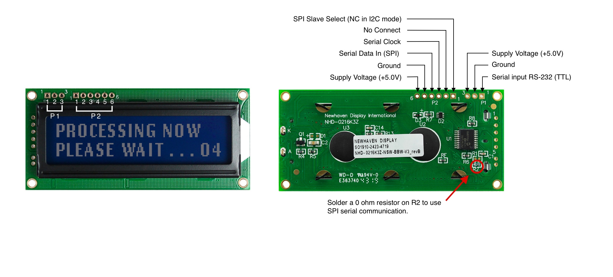
Descripción de los pines P1 - Comunicación RS232 TTL
| N.º de referencia | Símbolo | Descripción de la función |
|---|---|---|
| 1 | RX | Entrada serie RS-232 (TTL) |
| 2 | V SS | Suelo |
| 3 | V DD | Tensión de alimentación (+5,0 V) |
Descripción de los pines P2: comunicación SPI e I2C
| N.º de referencia | Símbolo | Descripción de la función |
|---|---|---|
| 1 | SPISS | Selección de esclavo SPI (NC en modo I2C) |
| 2 | SDO | Sin conexión |
| 3 | SCK/SCL | Reloj serie |
| 4 | SDI/SDA | Entrada de datos en serie (SPI) / Datos en serie (I2C) |
| 5 | V SS | Suelo |
| 6 | V DD | Tensión de alimentación (+5,0 V) |
La especificación completa de la disposición de pines de la pantalla LCD se puede consultar aquí.
Distribución de pines de Arduino
La placa Arduino UNO cuenta con 20 pines de entrada/salida, incluidos 14 pines digitales y 6 pines analógicos; para este proyecto, utilizaremos los pines de 5 V y GND de las señales de alimentación, los pines 10, 11 y 12 para SPI o I2C, y el pin 7 para RS232 TTL.
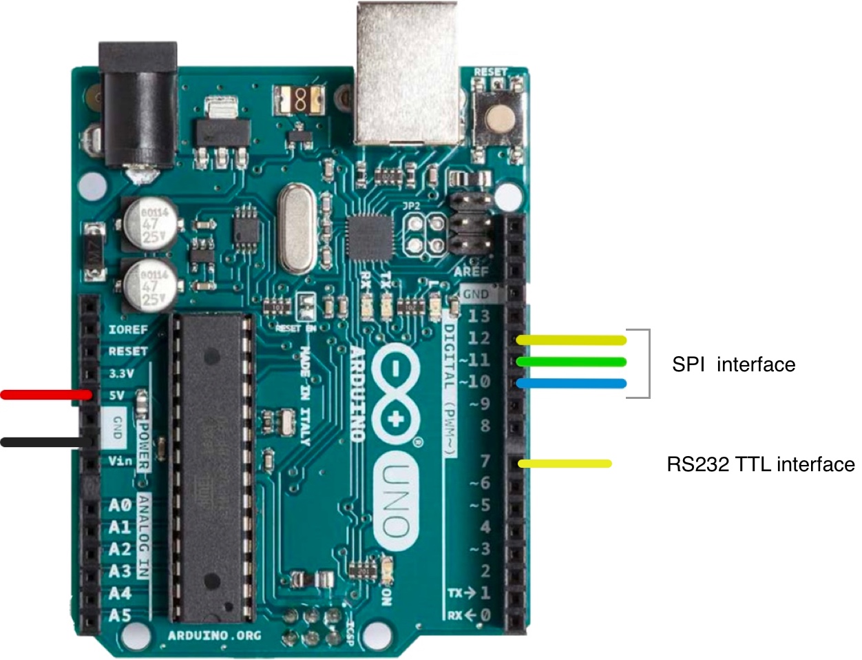
El esquema completo de la disposición de pines del Arduino UNO se puede consultar aquí.
Circuito: diagrama de conexiones y esquema para la comunicación SPI
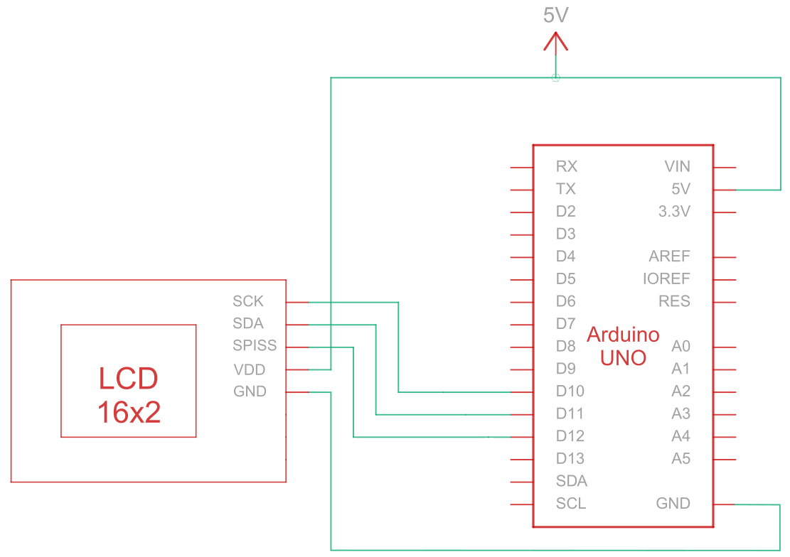
La interfaz periférica en serie (SPI) es un bus de comunicación en serie síncrono que se utiliza para la comunicación de alta velocidad a corta distancia entre varios dispositivos. El circuito de conexión para la comunicación SPI entre el Arduino (dispositivo maestro) y la pantalla LCD (dispositivo esclavo) utiliza cinco cables para comunicarse, tal y como se describe en la tabla siguiente:
| Arduino | LCD | Tipo de conexión |
|---|---|---|
| Pin de 5 V | Pin 6: V DD | Potencia |
| Clavija de tierra | Pin 5: Tierra | Suelo |
| Pin 10: Selección de esclavo | Pin 3: SCK/SCL | Reloj serie |
| Pin 11: MISO | Pin 4: Entrada de datos en serie (SPI) / Datos en serie (I2C) | Entrada de datos en serie |
| Pin 12: MOSI | Pin 1: SPISS | Selección de esclavo SPI |
Nota:
Para habilitar el SPI, es necesario que R1 esté abierto y que R2 se acorte tal y como se especifica en la ficha técnica. Además, antes de empezar, asegúrate de que el Arduino esté apagado mientras conectas el circuito.
Circuito de cableado SPI
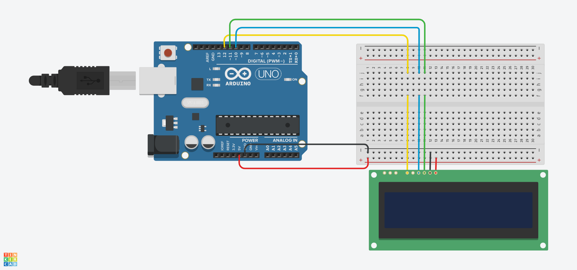
Esquema de cableado del SPI
Arduino: código de ejemplo para una pantalla LCD mediante la interfaz SPI
Los siguientes ejemplos de código muestran cómo utilizar la comunicación en serie entre Arduino y una pantalla LCD de 16x2 caracteres mediante la interfaz SPI. En los ejemplos de código encontrarás comentarios útiles, pero a continuación vamos a analizar algunas de las funciones:
- El
SPI_Out()La función envía comandos y datos a la pantalla LCD a través de SPI. Para ello, recorre los 8 bits del byte de entrada y envía el valor de cada bit a la pantalla LCD. - El
Set_Pins()Esta función configura los pines SPI como pines de salida. - El
Set_Contrast()Esta función ajusta el contraste de la pantalla LCD. - El
Set_Backlight()Esta función ajusta la retroiluminación de la pantalla LCD. - El
Clear_Display()Esta función borra la pantalla LCD. - El
Set_Cursor()Esta función activa o desactiva el parpadeo del cursor en la pantalla LCD, en función del parámetro de entrada. - El
setup()La función «function» es la función principal y se ejecuta una vez al iniciar el Arduino. Se utiliza para inicializar los ajustes y las variables, así como para ejecutar cualquier otra función y configuración necesaria para el proyecto. - El
loop()La función se ejecuta en un bucle continuo mientras la placa Arduino esté encendida. En algunos de los ejemplos que aparecen a continuación, esta función está vacía y no hace nada, ya que solo necesitamos ejecutar algunas funciones una vez.
Arduino - Ejemplos de código para pantallas LCD mediante SPI:
- ¡Hola, mundo!
- Mostrar el texto de la primera y la segunda fila
- Mostrar texto extenso
- Mostrar texto con un cursor parpadeante
- Cursor + texto con desplazamiento automático
- Desplazamiento automático
- Contraste
- Retroiluminación
- Tablas de caracteres/fuentes
Puedes adaptar y ampliar los ejemplos de código para que se ajusten a los requisitos específicos de tu proyecto basado en Arduino.
¡Hola, mundo!
El siguiente ejemplo de código muestra «Hello Word!» en la pantalla LCD.
/*  SPI Wiring Reference for: NHD-0216K3Z-NSW-BBW-V3
  ---------------------------
  LCD         |   Arduino
  ---------------------------
  1(SPISS)  --> 12
  2(SDO)    --> No Connect
  3(SCK)    --> 10
  4(SDA)    --> 11
  5(VSS)    --> Ground
  6(VDD)    --> 5V
*/
/*****************************************************
   Arduino pin definition
  /*****************************************************/
#define SPISS_PIN   12
#define SDA_PIN     11
#define SCK_PIN     10
/*****************************************************
   SPI function to send command and data.
   For more information on SPI please visit our Support Center
  /*****************************************************/
void SPI_Out(unsigned char a) {
  digitalWrite(SPISS_PIN, LOW);
  for (int n = 0; n < 8; n++) {
    if ((a & 0x80) == 0x80) {
      digitalWrite(SDA_PIN, HIGH);
      delayMicroseconds(200);
    }
    else {
      digitalWrite(SDA_PIN, LOW);
    }
    delayMicroseconds(200);
    a = a << 1;
    digitalWrite(SCK_PIN, LOW);
    digitalWrite(SCK_PIN, HIGH);
    delayMicroseconds(200);
  }
  digitalWrite(SCK_PIN, HIGH);
  delayMicroseconds(200);
  digitalWrite(SPISS_PIN, HIGH);
}
/*****************************************************
   Set Arduino UNO IO ports as Output mode
  /*****************************************************/
void Set_Pins() {
  pinMode(SPISS_PIN, OUTPUT);
  pinMode(SCK_PIN, OUTPUT);
  pinMode(SDA_PIN, OUTPUT);
}
/*****************************************************
   Set LCD Contrast
  /*****************************************************/
void Set_Contrast() {
  SPI_Out(0xFE);              //prefix command
  SPI_Out(0x52);              //contrast command
  SPI_Out(0x28);              //set contrast value
  delayMicroseconds(500);
}
/*****************************************************
   Set LCD Backlight
  /*****************************************************/
void Set_Backlight() {
  SPI_Out(0xFE);             //prefix command
  SPI_Out(0x53);             //backlight command
  SPI_Out(0x08);             //set backlight value
  delayMicroseconds(100);
}
/*****************************************************
   Clear LCD
  /*****************************************************/
void Clear_Display() {
  SPI_Out(0xFE);             //prefix command
  SPI_Out(0x51);             //clear display command
  delayMicroseconds(1500);
}
/*****************************************************
   Set cursor
   Mode = 0 sets Blinking cursor off
   Mode = 1 sets Blinking cursor on
  /*****************************************************/
void Set_Cursor(int mode) {
  SPI_Out(0xfe);          //prefix command
  if (mode == 0) {
    SPI_Out(0x4c);        //Blinking cursor off
  }
  else if (mode == 1) {
    SPI_Out(0x4b);        //Blinking cursor on
  }
  delayMicroseconds(100);
}
/*****************************************************
   Write "Hello World!" to LCD
  /*****************************************************/
void Hello_World() {
  SPI_Out(0x48); // H
  SPI_Out(0x65); // E
  SPI_Out(0x6C); // l
  SPI_Out(0x6C); // l
  SPI_Out(0x6F); // o
  SPI_Out(0x11); // Blank
  SPI_Out(0x57); // W
  SPI_Out(0x6f); // o
  SPI_Out(0x72); // r
  SPI_Out(0x6c); // l
  SPI_Out(0x64); // d
  SPI_Out(0x21); // !
}
/*****************************************************
     Main function
  /*****************************************************/
void setup() {
  Set_Pins();         //set IO ports
  Set_Cursor(0);      //turns off blinking cursor
  Set_Contrast();     //set display contrast
  Set_Backlight();    //set display backlight
  Clear_Display();    //clear display
  Hello_World();      //display "Hello World!"
}
void loop() {
}
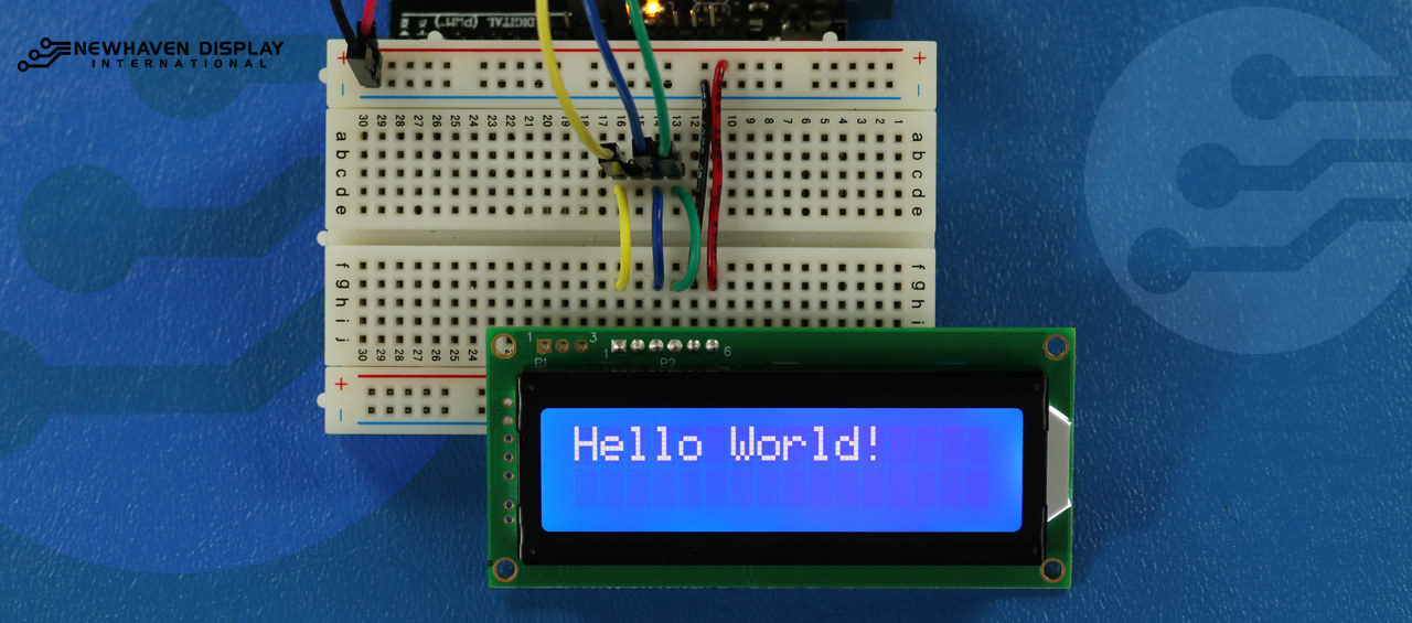
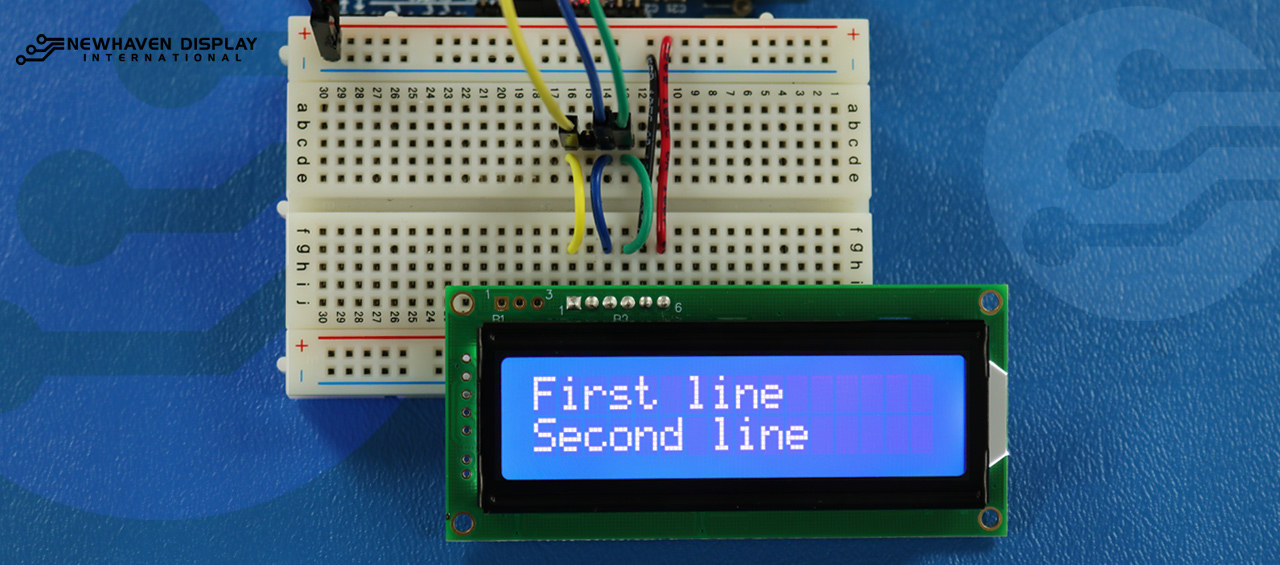
Mostrar el texto de la primera y la segunda fila
Este código mostrará el texto «Primera línea» en la primera fila y «Segunda línea» en la segunda fila.
/*****************************************************
  This code was written for the Arduino UNO using SPI Interface.
  This code displays text in row one and row two of LCD.
  /*  SPI Wiring Reference for: NHD-0216K3Z-NSW-BBW-V3
  ---------------------------
  LCD         |   Arduino
  ---------------------------
  1(SPISS)  --> 12
  2(SDO)    --> No Connect
  3(SCK)    --> 10
  4(SDA)    --> 11
  5(VSS)    --> Ground
  6(VDD)    --> 5V
*/
/*****************************************************
   Arduino pin definition
  /*****************************************************/
#define SPISS_PIN   12
#define SDA_PIN     11
#define SCK_PIN     10
/*****************************************************
   SPI function to send command and data.
   For more information on SPI please visit our Support Center
  /*****************************************************/
void SPI_Out(unsigned char a) {
  digitalWrite(SPISS_PIN, LOW);
  for (int n = 0; n < 8; n++) {
    if ((a & 0x80) == 0x80) {
      digitalWrite(SDA_PIN, HIGH);
      delayMicroseconds(200);
    }
    else {
      digitalWrite(SDA_PIN, LOW);
    }
    delayMicroseconds(200);
    a = a << 1;
    digitalWrite(SCK_PIN, LOW);
    digitalWrite(SCK_PIN, HIGH);
    delayMicroseconds(200);
  }
  digitalWrite(SCK_PIN, HIGH);
  delayMicroseconds(200);
  digitalWrite(SPISS_PIN, HIGH);
}
/*****************************************************
   Set Arduino UNO IO ports as Output mode
  /*****************************************************/
void Set_Pins() {
  pinMode(SPISS_PIN, OUTPUT);
  pinMode(SCK_PIN, OUTPUT);
  pinMode(SDA_PIN, OUTPUT);
}
/*****************************************************
   Set LCD Contrast
  /*****************************************************/
void Set_Contrast() {
  SPI_Out(0xFE);              //prefix command
  SPI_Out(0x52);              //contrast command
  SPI_Out(0x28);              //set contrast value
  delayMicroseconds(500);
}
/*****************************************************
   Set LCD Backlight
  /*****************************************************/
void Set_Backlight() {
  SPI_Out(0xFE);             //prefix command
  SPI_Out(0x53);             //backlight command
  SPI_Out(0x08);             //set backlight value
  delayMicroseconds(100);
}
/*****************************************************
   Clear LCD
  /*****************************************************/
void Clear_Display() {
  SPI_Out(0xFE);             //prefix command
  SPI_Out(0x51);             //clear display command
  delayMicroseconds(1500);
}
/*****************************************************
   Write "First Line" to row one on LCD
  /*****************************************************/
void Send_First_Line_Text() {
  SPI_Out(0x46); // F
  SPI_Out(0x69); // i
  SPI_Out(0x72); // r
  SPI_Out(0x73); // s
  SPI_Out(0x74); // t
  SPI_Out(0x20); // blank space
  SPI_Out(0x6c); // l
  SPI_Out(0x69); // i
  SPI_Out(0x6e); // n
  SPI_Out(0x65); // e
}
/*****************************************************
   Write "Second Line" to row two on LCD
  /*****************************************************/
void Send_Second_Line_Text() {
  SPI_Out(0x53); // S
  SPI_Out(0x65); // e
  SPI_Out(0x63); // c
  SPI_Out(0x6f); // o
  SPI_Out(0x6e); // n
  SPI_Out(0x64); // d
  SPI_Out(0x20); // blank space
  SPI_Out(0x6c); // l
  SPI_Out(0x69); // i
  SPI_Out(0x6e); // n
  SPI_Out(0x65); // e
}
/*****************************************************
   Set Row address
   Line = 1 sets for first row
   Line = 2 sets for second row
  /*****************************************************/
void Set_Row(int line) {
  SPI_Out(0xfe);      //prefix command
  SPI_Out(0x45);      //set cursor command
  if (line == 1) {
    SPI_Out(0x00);    //cursor position: row one, column one
  }
  else if (line == 2) {
    SPI_Out(0x40);    //cursor position: row two, column one
  }
  delayMicroseconds(100);
}
/*****************************************************
     Main function
  /*****************************************************/
void setup() {
  Set_Pins();         //set IO ports
  Set_Contrast();     //set display contrast
  Set_Backlight();    //set display backlight
  Clear_Display();    //clear display
  Set_Row(1);
  Send_First_Line_Text();       //writes to first line of display
  Set_Row(2);
  Send_Second_Line_Text();      //writes to second line of display
  delay(1000);
}
void loop() {
}
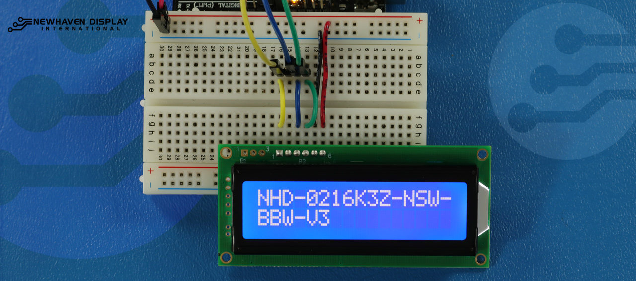
Mostrar texto extenso
Este código muestra un texto que se extiende hasta la segunda línea. En este ejemplo, mostraremos el texto «NHD-0216K3Z-NSW-BBW-V3».
/*****************************************************
  This code displays the part number: NHD-0216K3Z-NSW-BBW-V3.
  /*  SPI Wiring Reference for: NHD-0216K3Z-NSW-BBW-V3
  ---------------------------
  LCD         |   Arduino
  ---------------------------
  1(SPISS)  --> 12
  2(SDO)    --> No Connect
  3(SCK)    --> 10
  4(SDA)    --> 11
  5(VSS)    --> Ground
  6(VDD)    --> 5V
*/
/*****************************************************
   Arduino pin definition
  /*****************************************************/
#define SPISS_PIN   12
#define SDA_PIN     11
#define SCK_PIN     10
/*****************************************************
   SPI function to send command and data.
   For more information on SPI please visit our Support Center
  /*****************************************************/
void SPI_Out(unsigned char a) {
  digitalWrite(SPISS_PIN, LOW);
  for (int n = 0; n < 8; n++) {
    if ((a & 0x80) == 0x80) {
      digitalWrite(SDA_PIN, HIGH);
      delayMicroseconds(200);
    }
    else {
      digitalWrite(SDA_PIN, LOW);
    }
    delayMicroseconds(200);
    a = a << 1;
    digitalWrite(SCK_PIN, LOW);
    digitalWrite(SCK_PIN, HIGH);
    delayMicroseconds(200);
  }
  digitalWrite(SCK_PIN, HIGH);
  delayMicroseconds(200);
  digitalWrite(SPISS_PIN, HIGH);
}
/*****************************************************
   Set Arduino UNO IO ports as Output mode
  /*****************************************************/
void Set_Pins() {
  pinMode(SPISS_PIN, OUTPUT);
  pinMode(SCK_PIN, OUTPUT);
  pinMode(SDA_PIN, OUTPUT);
}
/*****************************************************
   Set LCD Contrast
  /*****************************************************/
void Set_Contrast() {
  SPI_Out(0xFE);              //prefix command
  SPI_Out(0x52);              //contrast command
  SPI_Out(0x28);              //set contrast value
  delayMicroseconds(500);
}
/*****************************************************
   Set LCD Backlight
  /*****************************************************/
void Set_Backlight() {
  SPI_Out(0xFE);             //prefix command
  SPI_Out(0x53);             //backlight command
  SPI_Out(0x08);             //set backlight value
  delayMicroseconds(100);
}
/*****************************************************
   Clear LCD
  /*****************************************************/
void Clear_Display() {
  SPI_Out(0xFE);             //prefix command
  SPI_Out(0x51);             //clear display command
  delayMicroseconds(1500);
}
/*****************************************************
   Set cursor
   Mode = 0 sets Blinking cursor off
   Mode = 1 sets Blinking cursor on
  /*****************************************************/
void Set_Cursor(int mode) {
  SPI_Out(0xfe);          //prefix command
  if (mode == 0) {
    SPI_Out(0x4c);        //Blinking cursor off
  }
  else if (mode == 1) {
    SPI_Out(0x4b);        //Blinking cursor on
  }
  delayMicroseconds(100);
}
/*****************************************************
   Set Row address
   Line = 1 sets for first row
   Line = 2 sets for second row
  /*****************************************************/
void Set_Row(int line) {
  SPI_Out(0xfe);      //prefix command
  SPI_Out(0x45);      //set cursor command
  if (line == 1) {
    SPI_Out(0x00);    //cursor position: row one, column one
  }
  else if (line == 2) {
    SPI_Out(0x40);    //cursor position: row two, column one
  }
  delayMicroseconds(100);
}
/*****************************************************
   Write "NHD-0216K3Z-NSW-BBW-V3" to LCD
  /*****************************************************/
void Part_Number() {
  Set_Row(1);
  SPI_Out(0x4e); // N
  SPI_Out(0x48); // H
  SPI_Out(0x44); // D
  SPI_Out(0xb0); // -
  SPI_Out(0x30); // 0
  SPI_Out(0x32); // 2
  SPI_Out(0x31); // 1
  SPI_Out(0x36); // 6
  SPI_Out(0x4b); // K
  SPI_Out(0x33); // 3
  SPI_Out(0x5a); // Z
  SPI_Out(0xb0); // -
  SPI_Out(0x4e); // N
  SPI_Out(0x53); // S
  SPI_Out(0x57); // W
  SPI_Out(0xb0); // -
  Set_Row(2);
  SPI_Out(0x42); // B
  SPI_Out(0x42); // B
  SPI_Out(0x57); // W
  SPI_Out(0xb0); // -
  SPI_Out(0x56); // V
  SPI_Out(0x33); // 3
}
/*****************************************************
     Main function
  /*****************************************************/
void setup() {
  Set_Pins();         //set IO ports
  Set_Cursor(0);      //turns off blinking cursor
  Set_Contrast();     //set display contrast
  Set_Backlight();    //set display backlight
  Clear_Display();    //clear display
  Part_Number();      //display "NHD-0216K3Z-NSW-BBW-V3"
}
void loop() {
}
Blink: mostrar texto con el cursor parpadeante
Este código muestra un texto con un cursor parpadeante. En este ejemplo, mostraremos el textoNHD-0216K3Z-NSW-BBW-V3».
/*****************************************************
  This code displays the part number: NHD-0216K3Z-NSW-BBW-V3 with cursor on.
  /*  SPI Wiring Reference for: NHD-0216K3Z-NSW-BBW-V3
  ---------------------------
  LCD         |   Arduino
  ---------------------------
  1(SPISS)  --> 12
  2(SDO)    --> No Connect
  3(SCK)    --> 10
  4(SDA)    --> 11
  5(VSS)    --> Ground
  6(VDD)    --> 5V
*/
/*****************************************************
   Arduino pin definition
  /*****************************************************/
#define SPISS_PIN   12
#define SDA_PIN     11
#define SCK_PIN     10
/*****************************************************
   SPI function to send command and data.
   For more information on SPI please visit our Support Center
  /*****************************************************/
void SPI_Out(unsigned char a) {
  digitalWrite(SPISS_PIN, LOW);
  for (int n = 0; n < 8; n++) {
    if ((a & 0x80) == 0x80) {
      digitalWrite(SDA_PIN, HIGH);
      delayMicroseconds(200);
    }
    else {
      digitalWrite(SDA_PIN, LOW);
    }
    delayMicroseconds(200);
    a = a << 1;
    digitalWrite(SCK_PIN, LOW);
    digitalWrite(SCK_PIN, HIGH);
    delayMicroseconds(200);
  }
  digitalWrite(SCK_PIN, HIGH);
  delayMicroseconds(200);
  digitalWrite(SPISS_PIN, HIGH);
}
/*****************************************************
   Set Arduino UNO IO ports as Output mode
  /*****************************************************/
void Set_Pins() {
  pinMode(SPISS_PIN, OUTPUT);
  pinMode(SCK_PIN, OUTPUT);
  pinMode(SDA_PIN, OUTPUT);
}
/*****************************************************
   Set LCD Contrast
  /*****************************************************/
void Set_Contrast() {
  SPI_Out(0xFE);              //prefix command
  SPI_Out(0x52);              //contrast command
  SPI_Out(0x28);              //set contrast value
  delayMicroseconds(500);
}
/*****************************************************
   Set LCD Backlight
  /*****************************************************/
void Set_Backlight() {
  SPI_Out(0xFE);             //prefix command
  SPI_Out(0x53);             //backlight command
  SPI_Out(0x08);             //set backlight value
  delayMicroseconds(100);
}
/*****************************************************
   Clear LCD
  /*****************************************************/
void Clear_Display() {
  SPI_Out(0xFE);             //prefix command
  SPI_Out(0x51);             //clear display command
  delayMicroseconds(1500);
}
/*****************************************************
   Set cursor
   Mode = 0 sets Blinking cursor off
   Mode = 1 sets Blinking cursor on
  /*****************************************************/
void Set_Cursor(int mode) {
  SPI_Out(0xfe);          //prefix command
  if (mode == 0) {
    SPI_Out(0x4c);        //Blinking cursor off
  }
  else if (mode == 1) {
    SPI_Out(0x4b);        //Blinking cursor on
  }
  delayMicroseconds(100);
}
/*****************************************************
   Set Row address
   Line = 1 sets for first row
   Line = 2 sets for second row
  /*****************************************************/
void Set_Row(int line) {
  SPI_Out(0xfe);      //prefix command
  SPI_Out(0x45);      //set cursor command
  if (line == 1) {
    SPI_Out(0x00);    //cursor position: row one, column one
  }
  else if (line == 2) {
    SPI_Out(0x40);    //cursor position: row two, column one
  }
  delayMicroseconds(100);
}
/*****************************************************
   Write "NHD-0216K3Z-NSW-BBW-V3" to LCD
   delay(500) = 500 Milliseconds
  /*****************************************************/
void Part_Number() {
  Set_Row(1);
  SPI_Out(0x4e); // N
  delay(500);
  SPI_Out(0x48); // H
  delay(500);
  SPI_Out(0x44); // D
  delay(500);
  SPI_Out(0xb0); // -
  delay(500);
  SPI_Out(0x30); // 0
  delay(500);
  SPI_Out(0x32); // 2
  delay(500);
  SPI_Out(0x31); // 1
  delay(500);
  SPI_Out(0x36); // 6
  delay(500);
  SPI_Out(0x4b); // K
  delay(500);
  SPI_Out(0x33); // 3
  delay(500);
  SPI_Out(0x5a); // Z
  delay(500);
  SPI_Out(0xb0); // -
  delay(500);
  SPI_Out(0x4e); // N
  delay(500);
  SPI_Out(0x53); // S
  delay(500);
  SPI_Out(0x57); // W
  delay(500);
  SPI_Out(0xb0); // -
  Set_Row(2);
  delay(500);
  SPI_Out(0x42); // B
  delay(500);
  SPI_Out(0x42); // B
  delay(500);
  SPI_Out(0x57); // W
  delay(500);
  SPI_Out(0xb0); // -
  delay(500);
  SPI_Out(0x56); // V
  delay(500);
  SPI_Out(0x33); // 3
}
/*****************************************************
     Main function
  /*****************************************************/
void setup() {
  Set_Pins();         //set IO ports
  Set_Contrast();     //set display contrast
  Set_Backlight();    //set display backlight
  Clear_Display();    //clear display
  Set_Cursor(1);      //turns on blinking cursor
  Part_Number();      //display "NHD-0216K3Z-NSW-BBW-V3"
}
void loop() {
}
Cursor + texto con desplazamiento automático
Este código muestra primero el texto con el cursor activado y, a continuación, inicializa el desplazamiento automático hacia la derecha.
/*****************************************************
  This code was written for the Arduino UNO using SPI Interface.
  This code displays the part number: NHD-0216K3Z-NSW-BBW-V3 while shifting to the right with a blinking cursor.
  /*  SPI Wiring Reference for: NHD-0216K3Z-NSW-BBW-V3
  ---------------------------
  LCD         |   Arduino
  ---------------------------
  1(SPISS)  --> 12
  2(SDO)    --> No Connect
  3(SCK)    --> 10
  4(SDA)    --> 11
  5(VSS)    --> Ground
  6(VDD)    --> 5V
*/
/*****************************************************
   Arduino pin definition
  /*****************************************************/
#define SPISS_PIN   12
#define SDA_PIN     11
#define SCK_PIN     10
/*****************************************************
   SPI function to send command and data.
   For more information on SPI please visit our Support Center
  /*****************************************************/
void SPI_Out(unsigned char a) {
  digitalWrite(SPISS_PIN, LOW);
  for (int n = 0; n < 8; n++) {
    if ((a & 0x80) == 0x80) {
      digitalWrite(SDA_PIN, HIGH);
      delayMicroseconds(200);
    }
    else {
      digitalWrite(SDA_PIN, LOW);
    }
    delayMicroseconds(200);
    a = a << 1;
    digitalWrite(SCK_PIN, LOW);
    digitalWrite(SCK_PIN, HIGH);
    delayMicroseconds(200);
  }
  digitalWrite(SCK_PIN, HIGH);
  delayMicroseconds(200);
  digitalWrite(SPISS_PIN, HIGH);
}
/*****************************************************
   Set Arduino UNO IO ports as Output mode
  /*****************************************************/
void Set_Pins() {
  pinMode(SPISS_PIN, OUTPUT);
  pinMode(SCK_PIN, OUTPUT);
  pinMode(SDA_PIN, OUTPUT);
}
/*****************************************************
   Set LCD Contrast
  /*****************************************************/
void Set_Contrast() {
  SPI_Out(0xFE);              //prefix command
  SPI_Out(0x52);              //contrast command
  SPI_Out(0x28);              //set contrast value
  delayMicroseconds(500);
}
/*****************************************************
   Set LCD Backlight
  /*****************************************************/
void Set_Backlight() {
  SPI_Out(0xFE);             //prefix command
  SPI_Out(0x53);             //backlight command
  SPI_Out(0x08);             //set backlight value
  delayMicroseconds(100);
}
/*****************************************************
   Clear LCD
  /*****************************************************/
void Clear_Display() {
  SPI_Out(0xFE);             //prefix command
  SPI_Out(0x51);             //clear display command
  delayMicroseconds(1500);
}
/*****************************************************
   Set cursor
   Mode = 0 sets Blinking cursor off
   Mode = 1 sets Blinking cursor on
  /*****************************************************/
void Set_Cursor(int mode) {
  SPI_Out(0xfe);          //prefix command
  if (mode == 0) {
    SPI_Out(0x4c);        //Blinking cursor off
  }
  else if (mode == 1) {
    SPI_Out(0x4b);        //Blinking cursor on
  }
  delayMicroseconds(100);
}
/*****************************************************
   Set Row address
   Line = 1 sets for first row
   Line = 2 sets for second row
  /*****************************************************/
void Set_Row(int line) {
  SPI_Out(0xfe);      //prefix command
  SPI_Out(0x45);      //set cursor command
  if (line == 1) {
    SPI_Out(0x00);    //cursor position: row one, column one
  }
  else if (line == 2) {
    SPI_Out(0x40);    //cursor position: row two, column one
  }
  delayMicroseconds(100);
}
/*****************************************************
   Write "NHD-0216K3Z-NSW-BBW-V3" to LCD
  /*****************************************************/
void Part_Number() {
    Set_Row(1);
  SPI_Out(0x4e); // N
  SPI_Out(0x48); // H
  SPI_Out(0x44); // D
  SPI_Out(0xb0); // -
  SPI_Out(0x30); // 0
  SPI_Out(0x32); // 2
  SPI_Out(0x31); // 1
  SPI_Out(0x36); // 6
  SPI_Out(0x4b); // K
  SPI_Out(0x33); // 3
  SPI_Out(0x5a); // Z
  SPI_Out(0xb0); // -
  SPI_Out(0x4e); // N
  SPI_Out(0x53); // S
  SPI_Out(0x57); // W
  SPI_Out(0xb0); // -
  Set_Row(2);
  SPI_Out(0x42); // B
  SPI_Out(0x42); // B
  SPI_Out(0x57); // W
  SPI_Out(0xb0); // -
  SPI_Out(0x56); // V
  SPI_Out(0x33); // 3
}
/*****************************************************
   Set Shifting mode
   Mode = 0 Move display one place to the left
   Mode = 1 Move display one place to the right
   delay(500) = 500 Milliseconds
  /*****************************************************/
void Set_Shift(int mode) {
  SPI_Out(0xfe);      //prefix command
  if (mode == 0) {
    SPI_Out(0x55);    //Move display one place to the left
  }
  else if (mode == 1) {
    SPI_Out(0x56);    //Move display one place to the right
  }
  delay(500);
}
/*****************************************************
     Main function
  /*****************************************************/
void setup() {
  Set_Pins();         //set IO ports
  Set_Contrast();     //set display contrast
  Set_Backlight();    //set display backlight
  Clear_Display();    //clear display
  Set_Cursor(1);      //turns on blinking cursor
  Part_Number();      //display "NHD-0216K3Z-NSW-BBW-V3"
}
/*****************************************************
     Loop function
  /*****************************************************/
void loop() {
  Set_Shift(1);     //shift display to the right
}
Texto con desplazamiento automático
Este código hace que el texto «NHD-0216K3Z-NSW-BBW-V3» se desplace automáticamente.
/*****************************************************
  This code was written for the Arduino UNO using SPI Interface.
  This code displays the part number: NHD-0216K3Z-NSW-BBW-V3 while shifting to the right.
  /*  SPI Wiring Reference for: NHD-0216K3Z-NSW-BBW-V3
  ---------------------------
  LCD         |   Arduino
  ---------------------------
  1(SPISS)  --> 12
  2(SDO)    --> No Connect
  3(SCK)    --> 10
  4(SDA)    --> 11
  5(VSS)    --> Ground
  6(VDD)    --> 5V
*/
/*****************************************************
   Arduino pin definition
  /*****************************************************/
#define SPISS_PIN   12
#define SDA_PIN     11
#define SCK_PIN     10
/*****************************************************
   SPI function to send command and data.
   For more information on SPI please visit our Support Center
  /*****************************************************/
void SPI_Out(unsigned char a) {
  digitalWrite(SPISS_PIN, LOW);
  for (int n = 0; n < 8; n++) {
    if ((a & 0x80) == 0x80) {
      digitalWrite(SDA_PIN, HIGH);
      delayMicroseconds(200);
    }
    else {
      digitalWrite(SDA_PIN, LOW);
    }
    delayMicroseconds(200);
    a = a << 1;
    digitalWrite(SCK_PIN, LOW);
    digitalWrite(SCK_PIN, HIGH);
    delayMicroseconds(200);
  }
  digitalWrite(SCK_PIN, HIGH);
  delayMicroseconds(200);
  digitalWrite(SPISS_PIN, HIGH);
}
/*****************************************************
   Set Arduino UNO IO ports as Output mode
  /*****************************************************/
void Set_Pins() {
  pinMode(SPISS_PIN, OUTPUT);
  pinMode(SCK_PIN, OUTPUT);
  pinMode(SDA_PIN, OUTPUT);
}
/*****************************************************
   Set LCD Contrast
  /*****************************************************/
void Set_Contrast() {
  SPI_Out(0xFE);              //prefix command
  SPI_Out(0x52);              //contrast command
  SPI_Out(0x28);              //set contrast value
  delayMicroseconds(500);
}
/*****************************************************
   Set LCD Backlight
  /*****************************************************/
void Set_Backlight() {
  SPI_Out(0xFE);             //prefix command
  SPI_Out(0x53);             //backlight command
  SPI_Out(0x08);             //set backlight value
  delayMicroseconds(100);
}
/*****************************************************
   Clear LCD
  /*****************************************************/
void Clear_Display() {
  SPI_Out(0xFE);             //prefix command
  SPI_Out(0x51);             //clear display command
  delayMicroseconds(1500);
}
/*****************************************************
   Set cursor
   Mode = 0 sets Blinking cursor off
   Mode = 1 sets Blinking cursor on
  /*****************************************************/
void Set_Cursor(int mode) {
  SPI_Out(0xfe);          //prefix command
  if (mode == 0) {
    SPI_Out(0x4c);        //Blinking cursor off
  }
  else if (mode == 1) {
    SPI_Out(0x4b);        //Blinking cursor on
  }
  delayMicroseconds(100);
}
/*****************************************************
   Set Row address
   Line = 1 sets for first row
   Line = 2 sets for second row
  /*****************************************************/
void Set_Row(int line) {
  SPI_Out(0xfe);      //prefix command
  SPI_Out(0x45);      //set cursor command
  if (line == 1) {
    SPI_Out(0x00);    //cursor position: row one, column one
  }
  else if (line == 2) {
    SPI_Out(0x40);    //cursor position: row two, column one
  }
  delayMicroseconds(100);
}
/*****************************************************
   Write "NHD-0216K3Z-NSW-BBW-V3" to LCD
  /*****************************************************/
void Part_Number() {
    Set_Row(1);
  SPI_Out(0x4e); // N
  SPI_Out(0x48); // H
  SPI_Out(0x44); // D
  SPI_Out(0xb0); // -
  SPI_Out(0x30); // 0
  SPI_Out(0x32); // 2
  SPI_Out(0x31); // 1
  SPI_Out(0x36); // 6
  SPI_Out(0x4b); // K
  SPI_Out(0x33); // 3
  SPI_Out(0x5a); // Z
  SPI_Out(0xb0); // -
  SPI_Out(0x4e); // N
  SPI_Out(0x53); // S
  SPI_Out(0x57); // W
  SPI_Out(0xb0); // -
  Set_Row(2);
  SPI_Out(0x42); // B
  SPI_Out(0x42); // B
  SPI_Out(0x57); // W
  SPI_Out(0xb0); // -
  SPI_Out(0x56); // V
  SPI_Out(0x33); // 3
}
/*****************************************************
   Set Shifting mode
   Mode = 0 Move display one place to the left
   Mode = 1 Move display one place to the right
   delay(500) = 500 Milliseconds
  /*****************************************************/
void Set_Shift(int mode) {
  SPI_Out(0xfe);      //prefix command
  if (mode == 0) {
    SPI_Out(0x55);    //Move display one place to the left
  }
  else if (mode == 1) {
    SPI_Out(0x56);    //Move display one place to the right
  }
  delay(500);
}
/*****************************************************
     Main function
  /*****************************************************/
void setup() {
  Set_Pins();         //set IO ports
  Set_Contrast();     //set display contrast
  Set_Backlight();    //set display backlight
  Clear_Display();    //clear display
  Set_Cursor(0);      //turns off blinking cursor
  Part_Number();      //display "NHD-0216K3Z-NSW-BBW-V3"
}
/*****************************************************
     Loop function
  /*****************************************************/
void loop() {
  Set_Shift(1);     //shift display to the right
}
Ajustar el contraste de la pantalla LCD
Este código muestra el texto «NHD-0216K3Z-NSW-BBW-V3» al ajustar el contraste.
    /*****************************************************
  This code was written for the Arduino UNO using SPI Interface.
  This code displays the part number: NHD-0216K3Z-NSW-BBW-V3 while changing the contrast.
  /*  SPI Wiring Reference for: NHD-0216K3Z-NSW-BBW-V3
  ---------------------------
  LCD         |   Arduino
  ---------------------------
  1(SPISS)  --> 12
  2(SDO)    --> No Connect
  3(SCK)    --> 10
  4(SDA)    --> 11
  5(VSS)    --> Ground
  6(VDD)    --> 5V
*/
/*****************************************************
   Arduino pin definition
  /*****************************************************/
#define SPISS_PIN   12
#define SDA_PIN     11
#define SCK_PIN     10
/*****************************************************
   SPI function to send command and data.
   For more information on SPI please visit our Support Center
  /*****************************************************/
void SPI_Out(unsigned char a) {
  digitalWrite(SPISS_PIN, LOW);
  for (int n = 0; n < 8; n++) {
    if ((a & 0x80) == 0x80) {
      digitalWrite(SDA_PIN, HIGH);
      delayMicroseconds(200);
    }
    else {
      digitalWrite(SDA_PIN, LOW);
    }
    delayMicroseconds(200);
    a = a << 1;
    digitalWrite(SCK_PIN, LOW);
    digitalWrite(SCK_PIN, HIGH);
    delayMicroseconds(200);
  }
  digitalWrite(SCK_PIN, HIGH);
  delayMicroseconds(200);
  digitalWrite(SPISS_PIN, HIGH);
}
/*****************************************************
   Set Arduino UNO IO ports as Output mode
  /*****************************************************/
void Set_Pins() {
  pinMode(SPISS_PIN, OUTPUT);
  pinMode(SCK_PIN, OUTPUT);
  pinMode(SDA_PIN, OUTPUT);
}
/*****************************************************
   Set LCD Contrast
  /*****************************************************/
void Set_Contrast() {
  SPI_Out(0xFE);              //prefix command
  SPI_Out(0x52);              //contrast command
  SPI_Out(0x32);              //set contrast value
  delayMicroseconds(500);
}
/*****************************************************
   Set LCD Backlight
  /*****************************************************/
void Set_Backlight() {
  SPI_Out(0xFE);             //prefix command
  SPI_Out(0x53);             //backlight command
  SPI_Out(0x08);             //set backlight value
  delayMicroseconds(100);
}
/*****************************************************
   Clear LCD
  /*****************************************************/
void Clear_Display() {
  SPI_Out(0xFE);             //prefix command
  SPI_Out(0x51);             //clear display command
  delayMicroseconds(1500);
}
/*****************************************************
   Set cursor
   Mode = 0 sets Blinking cursor off
   Mode = 1 sets Blinking cursor on
  /*****************************************************/
void Set_Cursor(int mode) {
  SPI_Out(0xfe);          //prefix command
  if (mode == 0) {
    SPI_Out(0x4c);        //Blinking cursor off
  }
  else if (mode == 1) {
    SPI_Out(0x4b);        //Blinking cursor on
  }
  delayMicroseconds(100);
}
/*****************************************************
   Set Row address
   Line = 1 sets for first row
   Line = 2 sets for second row
  /*****************************************************/
void Set_Row(int line) {
  SPI_Out(0xfe);      //prefix command
  SPI_Out(0x45);      //set cursor command
  if (line == 1) {
    SPI_Out(0x00);    //cursor position: row one, column one
  }
  else if (line == 2) {
    SPI_Out(0x40);    //cursor position: row two, column one
  }
  delayMicroseconds(100);
}
/*****************************************************
   Write "NHD-0216K3Z-NSW-BBW-V3" to LCD
  /*****************************************************/
void Part_Number() {
  Set_Row(1);
  SPI_Out(0x4e); // N
  SPI_Out(0x48); // H
  SPI_Out(0x44); // D
  SPI_Out(0xb0); // -
  SPI_Out(0x30); // 0
  SPI_Out(0x32); // 2
  SPI_Out(0x31); // 1
  SPI_Out(0x36); // 6
  SPI_Out(0x4b); // K
  SPI_Out(0x33); // 3
  SPI_Out(0x5a); // Z
  SPI_Out(0xb0); // -
  SPI_Out(0x4e); // N
  SPI_Out(0x53); // S
  SPI_Out(0x57); // W
  SPI_Out(0xb0); // -
  Set_Row(2);
  SPI_Out(0x42); // B
  SPI_Out(0x42); // B
  SPI_Out(0x57); // W
  SPI_Out(0xb0); // -
  SPI_Out(0x56); // V
  SPI_Out(0x33); // 3
}
/*****************************************************
  Function to:
    - change contrast from highest --> lowest
    - change contrast from lowest  --> highest
  delay(100) = 100 Milliseconds
  /*****************************************************/
void Contrast_Cycle() {
  for (int x = 50; x >= 0; x--) {
    SPI_Out(0xFE);             //High to Low contrast loop
    SPI_Out(0x52);
    SPI_Out(x);
    delay(100);
  }
  for (int x = 0; x <= 50; x++) {
    SPI_Out(0xFE);             //Low to High contrats loop
    SPI_Out(0x52);
    SPI_Out(x);
    delay(100);
  }
}
/*****************************************************
     Main function
  /*****************************************************/
void setup() {
  Set_Pins();         //set IO ports
  Set_Contrast();     //set display contrast
  Set_Backlight();    //set display backlight
  Clear_Display();    //clear display
  Set_Cursor(0);      //turns off blinking cursor
  Part_Number();      //display "NHD-0216K3Z-NSW-BBW-V3"
}
/*****************************************************
     Loop function
  /*****************************************************/
void loop() {
  Contrast_Cycle(); //cycle through contrast
}
Cómo utilizar la retroiluminación de la pantalla LCD
Existen diferentes métodos para controlar o ajustar la retroiluminación de la pantalla LCD. Dos de las formas más habituales de controlar o ajustar la retroiluminación de la pantalla LCD son mediante un comando o un potenciómetro.
En nuestras pantallas en serie, como la NHD-0216K3Z-NSW-BBW-V3, la retroiluminación se puede controlar mediante un comando. El Backlight_loop() La función ajusta el valor de brillo de la retroiluminación de mayor a menor y, a continuación, de menor a mayor, en un bucle continuo.
El código que aparece a continuación muestra el texto «NHD-0216K3Z-NSW-BBW-V3» al modificar la intensidad de la retroiluminación.
        /*****************************************************
  This code was written for the Arduino UNO using SPI Interface.
  This code displays the part number: NHD-0216K3Z-NSW-BBW-V3 while changing the backlight.
  /*  SPI Wiring Reference for: NHD-0216K3Z-NSW-BBW-V3
  ---------------------------
  LCD         |   Arduino
  ---------------------------
  1(SPISS)  --> 12
  2(SDO)    --> No Connect
  3(SCK)    --> 10
  4(SDA)    --> 11
  5(VSS)    --> Ground
  6(VDD)    --> 5V
*/
/*****************************************************
   Arduino pin definition
  /*****************************************************/
#define SPISS_PIN   12
#define SDA_PIN     11
#define SCK_PIN     10
/*****************************************************
   SPI function to send command and data.
   For more information on SPI please visit our Support Center
  /*****************************************************/
void SPI_OUT(unsigned char a) {
  digitalWrite(SPISS_PIN, LOW);
  for (int n = 0; n < 8; n++) {
    if ((a & 0x80) == 0x80) {
      digitalWrite(SDA_PIN, HIGH);
      delayMicroseconds(200);
    }
    else {
      digitalWrite(SDA_PIN, LOW);
    }
    delayMicroseconds(200);
    a = a << 1;
    digitalWrite(SCK_PIN, LOW);
    digitalWrite(SCK_PIN, HIGH);
    delayMicroseconds(200);
  }
  digitalWrite(SCK_PIN, HIGH);
  delayMicroseconds(200);
  digitalWrite(SPISS_PIN, HIGH);
}
/*****************************************************
   Set Arduino UNO IO ports as Output mode
  /*****************************************************/
void Set_Pins() {
  pinMode(SPISS_PIN, OUTPUT);
  pinMode(SCK_PIN, OUTPUT);
  pinMode(SDA_PIN, OUTPUT);
}
/*****************************************************
   Set LCD Contrast
  /*****************************************************/
void Set_Contrast() {
  SPI_OUT(0xFE);              //prefix command
  SPI_OUT(0x52);              //contrast command
  SPI_OUT(0x28);              //set contrast value
  delayMicroseconds(500);
}
/*****************************************************
   Set LCD Backlight
  /*****************************************************/
void Set_Backlight() {
  SPI_OUT(0xFE);             //prefix command
  SPI_OUT(0x53);             //backlight command
  SPI_OUT(0x08);             //set backlight value
  delayMicroseconds(100);
}
/*****************************************************
   Clear LCD
  /*****************************************************/
void Clear_Display() {
  SPI_OUT(0xFE);             //prefix command
  SPI_OUT(0x51);             //clear display command
  delayMicroseconds(1500);
}
/*****************************************************
   Set cursor
   Mode = 0 sets Blinking cursor off
   Mode = 1 sets Blinking cursor on
  /*****************************************************/
void Set_Cursor(int mode) {
  SPI_OUT(0xfe);          //prefix command
  if (mode == 0) {
    SPI_OUT(0x4c);        //Blinking cursor off
  }
  else if (mode == 1) {
    SPI_OUT(0x4b);        //Blinking cursor on
  }
  delayMicroseconds(100);
}
/*****************************************************
   Set Row address
   Line = 1 sets for first row
   Line = 2 sets for second row
  /*****************************************************/
void Set_Row(int line) {
  SPI_OUT(0xfe);      //prefix command
  SPI_OUT(0x45);      //set cursor command
  if (line == 1) {
    SPI_OUT(0x00);    //cursor position: row one, column one
  }
  else if (line == 2) {
    SPI_OUT(0x40);    //cursor position: row two, column one
  }
  delayMicroseconds(100);
}
/*****************************************************
   Write "NHD-0216K3Z-NSW-BBW-V3" to LCD
  /*****************************************************/
void Part_Number() {
    Set_Row(1);
  SPI_OUT(0x4e); // N
  SPI_OUT(0x48); // H
  SPI_OUT(0x44); // D
  SPI_OUT(0xb0); // -
  SPI_OUT(0x30); // 0
  SPI_OUT(0x32); // 2
  SPI_OUT(0x31); // 1
  SPI_OUT(0x36); // 6
  SPI_OUT(0x4b); // K
  SPI_OUT(0x33); // 3
  SPI_OUT(0x5a); // Z
  SPI_OUT(0xb0); // -
  SPI_OUT(0x4e); // N
  SPI_OUT(0x53); // S
  SPI_OUT(0x57); // W
  SPI_OUT(0xb0); // -
  Set_Row(2);
  SPI_OUT(0x42); // B
  SPI_OUT(0x42); // B
  SPI_OUT(0x57); // W
  SPI_OUT(0xb0); // -
  SPI_OUT(0x56); // V
  SPI_OUT(0x33); // 3
}
/*****************************************************
  Function to:
    - change backlight from highest --> lowest
    - change backlight from lowest  --> highest
  delay(500) = 500 Milliseconds
  /*****************************************************/
void Backlight_loop() {
  for (int x = 8; x >= 0; x--) {
    SPI_OUT(0xFE);              //High to Low Backlight loop
    SPI_OUT(0x53);
    SPI_OUT(x);
    delay(500);
  }
  for (int x = 0; x <= 8; x++) {
    SPI_OUT(0xFE);              //Low to High Backlight loop
    SPI_OUT(0x53);
    SPI_OUT(x);
    delay(500);
  }
}
/*****************************************************
     Main function
  /*****************************************************/
void setup() {
  Set_Pins();         //set IO ports
  Set_Contrast();     //set display contrast
  Set_Backlight();    //set display backlight
  Clear_Display();    //clear display
  Set_Cursor(0);      //turns off blinking cursor
  Part_Number();      //display "NHD-0216K3Z-NSW-BBW-V3"
}
/*****************************************************
     Loop function
  /*****************************************************/
void loop() {
  Backlight_loop();   //High to Low Backlight loop
}
Tablas de caracteres/fuentes
Este código muestra los caracteres de la tabla de fuentes incluida en la pantalla LCD.
        /*****************************************************
  This code was written for the Arduino UNO using SPI Interface.
  This code displays the font table characters.
  /*  SPI Wiring Reference for: NHD-0216K3Z-NSW-BBW-V3
  ---------------------------
  LCD         |   Arduino
  ---------------------------
  1(SPISS)  --> 12
  2(SDO)    --> No Connect
  3(SCK)    --> 10
  4(SDA)    --> 11
  5(VSS)    --> Ground
  6(VDD)    --> 5V
*/
/*****************************************************
   Arduino pin definition
  /*****************************************************/
#define SPISS_PIN   12
#define SDA_PIN     11
#define SCK_PIN     10
/*****************************************************
   SPI function to send command and data.
   For more information on SPI please visit our Support Center
  /*****************************************************/
void SPI_out(unsigned char a) {
  digitalWrite(SPISS_PIN, LOW);
  for (int n = 0; n < 8; n++) {
    if ((a & 0x80) == 0x80) {
      digitalWrite(SDA_PIN, HIGH);
      delayMicroseconds(200);
    }
    else {
      digitalWrite(SDA_PIN, LOW);
    }
    delayMicroseconds(200);
    a = a << 1;
    digitalWrite(SCK_PIN, LOW);
    digitalWrite(SCK_PIN, HIGH);
    delayMicroseconds(200);
  }
  digitalWrite(SCK_PIN, HIGH);
  delayMicroseconds(200);
  digitalWrite(SPISS_PIN, HIGH);
}
/*****************************************************
   Set Arduino UNO IO ports as Output mode
  /*****************************************************/
void Set_Pins() {
  pinMode(SPISS_PIN, OUTPUT);
  pinMode(SCK_PIN, OUTPUT);
  pinMode(SDA_PIN, OUTPUT);
}
/*****************************************************
   Set LCD Contrast
  /*****************************************************/
void Set_Contrast() {
  SPI_out(0xFE);              //prefix command
  SPI_out(0x52);              //contrast command
  SPI_out(0x28);              //set contrast value
  delayMicroseconds(500);
}
/*****************************************************
   Set LCD Backlight
  /*****************************************************/
void Set_Backlight() {
  SPI_out(0xFE);             //prefix command
  SPI_out(0x53);             //backlight command
  SPI_out(0x08);             //set backlight value
  delayMicroseconds(100);
}
/*****************************************************
   Clear LCD
  /*****************************************************/
void Clear_Display() {
  SPI_out(0xFE);             //prefix command
  SPI_out(0x51);             //clear display command
  delayMicroseconds(1500);
}
/*****************************************************
   Set cursor
   Mode = 0 sets Blinking cursor off
   Mode = 1 sets Blinking cursor on
  /*****************************************************/
void Set_Cursor(int mode) {
  SPI_out(0xfe);          //prefix command
  if (mode == 0) {
    SPI_out(0x4c);        //Blinking cursor off
  }
  else if (mode == 1) {
    SPI_out(0x4b);        //Blinking cursor on
  }
  delayMicroseconds(100);
}
/*****************************************************
   Set Row address
   Line = 1 sets for first row
   Line = 2 sets for second row
  /*****************************************************/
void Set_Row(int line) {
  SPI_out(0xfe);      //prefix command
  SPI_out(0x45);      //set cursor command
  if (line == 1) {
    SPI_out(0x00);    //cursor position: row one, column one
  }
  else if (line == 2) {
    SPI_out(0x40);    //cursor position: row two, column one
  }
  delayMicroseconds(100);
}
/*****************************************************
  Display font characters
    -change the row address every 16 characters displayed
    -used Clear_Display() function to clear the display
     and change the row to the first row
  delay(500) = 500 Milliseconds
  /*****************************************************/
void Font_Table_Characters() {
  Clear_Display();
  for (int i = 0; i < 64; i++) {
    if (i == 16 || i == 48) {
      Set_Row(2);
    }
    else if (i == 32 || i == 64) {
      Clear_Display();
      if (i == 64) {
        i = 0;
      }
    }
    SPI_out(i + 32);
    delay(500);
  }
}
/*****************************************************
     Main function
  /*****************************************************/
void setup() {
  Set_Pins();         //set IO ports
  Set_Contrast();     //set display contrast
  Set_Backlight();    //set display backlight
  Clear_Display();    //clear display
  Set_Cursor(0);      //turns off blinking cursor
}
/*****************************************************
     Loop function
  /*****************************************************/
void loop() {
  Font_Table_Characters();  //Display font characters
}
Circuito: diagrama de conexiones y esquema para la comunicación RS232 TTL
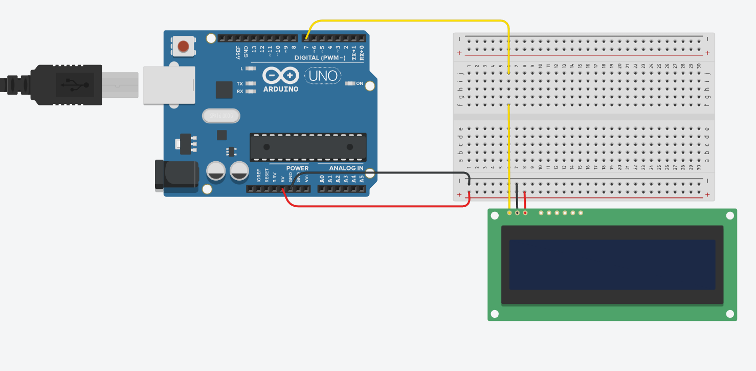
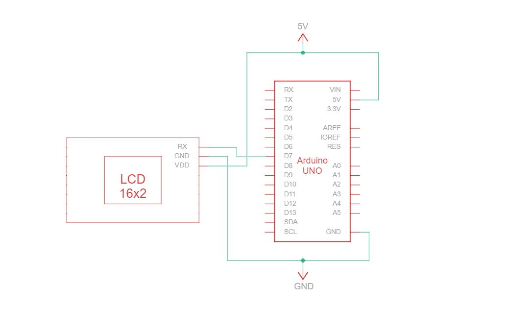
RS232 TTL es un protocolo de comunicación en serie que utiliza las especificaciones del tipo RS232, pero con niveles lógicos TTL (de 0 V a Vcc, normalmente 3,3 V o 5 V). El circuito de conexión RS232 TTL entre Arduino y la pantalla Newhaven de 16 caracteres utiliza solo tres cables:
| Arduino | LCD | Tipo de conexión |
|---|---|---|
| Pin de 5 V | Pin 3: V DD | Potencia |
| Clavija de tierra | Pin 2: Masa | Suelo |
| Pin 7: Pin de E/S digital | Pin 1: RX | Puerto de entrada serie RS-232 (TTL) |
Nota:
Los pines R1 y R2 de la pantalla deben estar abiertos para habilitar el modo RS232 TTL, tal y como se especifica en la ficha técnica.
Circuito de cableado RS232 TTL
Esquema de cableado RS232 TTL
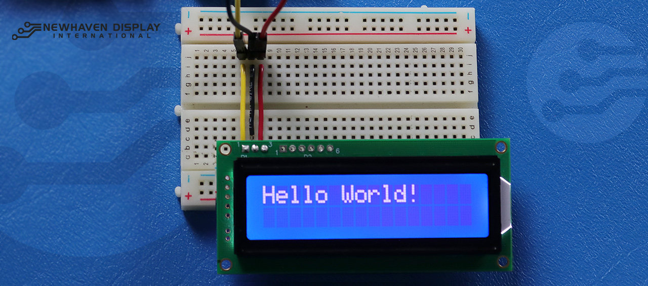
Hemos creado un tutorial detallado y apto para principiantes en Instructables sobre la comunicación RS232 TTL. El tutorial incluye todos los pasos necesarios para llevar a cabo este proyecto. Échale un vistazo aquí: www.instructables.com/Arduino-LCD-Tutorial/
Arduino - «Hello World» en pantalla LCD: ejemplo de código con comunicación serie RS232 TTL
El siguiente ejemplo de código muestra «Hello Word!» en la pantalla LCD mediante comunicación RS232 TTL.
/***************************************************** Este código se ha escrito para el Arduino UNO utilizando la interfaz RS-232. /* Referencia de cableado RS-232 para: NHD-0216K3Z-NSW-BBW-V3 --------------------------- LCD | Arduino --------------------------- 1(RX) --> 7 2(VSS) --> Masa 3(VDD) --> 5 V */ #define P1 7 //RX: el pin en el que se reciben los datos en serie. /***************************************************** Configuración RS-232 para comandos y datos. Para obtener más información sobre RS-232, visita nuestro Centro de asistencia /*****************************************************/ #include#define RxPin P1 SoftwareSerial NHD_LCD = SoftwareSerial(P1, RxPin); /***************************************************** Set LCD Contrast /*****************************************************/ void Set_Contrast() { NHD_LCD.write(0xFE); //Prefix command NHD_LCD.write(0x52); //Contrast command NHD_LCD.write(0x28); //Set contrast value delayMicroseconds(500); } /***************************************************** Clear LCD /*****************************************************/ void Clear_display() { NHD_LCD.write(0xFE); //Prefix command NHD_LCD.write(0x51); //Clear Display delayMicroseconds(1500); } /***************************************************** Set Arduino UNO IO ports as Output mode /*****************************************************/ void Set_Pins() { pinMode(RxPin, OUTPUT); } /***************************************************** Set LCD Backlight /*****************************************************/ void Set_Backlight() { NHD_LCD.write(0xFE); //prefix command NHD_LCD.write(0x53); //Backlight command NHD_LCD.write(0x08); //Set backlight value delayMicroseconds(100); } /***************************************************** Set cursor Mode = 0 sets Blinking cursor off Mode = 1 sets Blinking cursor on /*****************************************************/ void Set_Cursor(int mode) { NHD_LCD.write(0xFE); //Prefix command if (mode == 0) { NHD_LCD.write(0x4c); //Turn blinking cursor off } else if (mode == 1) { NHD_LCD.write(0x4b); //Turn blinking cursor on } delayMicroseconds(100); } /***************************************************** Write "Hello World!" to LCD /*****************************************************/ void Hello_World() { NHD_LCD.write(0x48); // H NHD_LCD.write(0x65); // e NHD_LCD.write(0x6C); // l NHD_LCD.write(0x6C); // l NHD_LCD.write(0x6F); // o NHD_LCD.write(0x11); // Blank NHD_LCD.write(0x57); // W NHD_LCD.write(0x6f); // o NHD_LCD.write(0x72); // r NHD_LCD.write(0x6c); // l NHD_LCD.write(0x64); // d NHD_LCD.write(0x21); // ! } /***************************************************** Main function /*****************************************************/ void setup() { NHD_LCD.begin(9600); //Sets 9600 Baud Rate the display can receive and transmit data at a rate of 9600 bits per second by default. delay(15); Set_Pins(); //Set IO ports Set_Cursor(0); //Turns off blinking cursor Set_Contrast(); //Set display Contrast Set_Backlight(); //Set display Backlight Clear_display(); //Clear display Hello_World(); //Display "Hello Wolrd!" } void loop() { }
Solución de problemas de tu pantalla LCD - Proyecto Arduino
A continuación, vamos a explicar algunos pasos habituales que debes seguir si te encuentras con dificultades o problemas en tu proyecto de Arduino con pantalla LCD.
- Comprueba las conexiones de cableado: el problema más habitual al conectar una pantalla LCD a un Arduino es un cableado incorrecto. Comprueba las conexiones del cableado comparándolas con el diagrama de pinout y el esquema de circuitos proporcionados para garantizar una conectividad adecuada. Además, ten en cuenta que la NHD-0216K3Z-NSW-BBW-V3 se puede configurar para funcionar con interfaces SPI, I2C y RS232 TTL. Para que funcione con la interfaz SPI, es necesario soldar una resistencia de 0 ohmios en la sección R2 de la placa de circuito impreso.
- Revisa los componentes: comprueba si hay algún signo visible de daño en el Arduino, la pantalla LCD o los cables de conexión.
- Comprueba el código: Asegúrate de que el código cargado en tu Arduino sea correcto y no contenga errores.
- Comprueba la fuente de alimentación: asegúrate de que la fuente de alimentación sea suficiente para alimentar tanto el Arduino como la pantalla LCD.
- Prueba con una pantalla LCD que sepas que funciona bien: si sigues teniendo problemas, prueba a conectar a tu Arduino otra pantalla LCD que sepas que funciona bien. Esto te ayudará a determinar si el problema está en la pantalla LCD o en la propia placa Arduino.
- Ajustar el contraste: Si tienes problemas para ver el texto que aparece en la pantalla LCD, prueba a ajustar el contraste mediante la función del software
Set_Contrast(), tal y como se ha descrito anteriormente. Las distintas condiciones de iluminación pueden requerir diferentes ajustes de contraste para lograr una visibilidad óptima. - Comprueba la versión del IDE de Arduino: asegúrate de que estás utilizando la última versión del IDE de Arduino. Las versiones obsoletas pueden contener errores o ser incompatibles con tu proyecto.
- Prueba funciones concretas: si tienes problemas con funciones específicas, como el desplazamiento o el control del contraste, prueba a ejecutar un código más sencillo, como el ejemplo «¡Hola, mundo!», para aislar el problema. Esto puede ayudarte a determinar si el problema está relacionado con el código o con el hardware.
- Pide ayuda a la comunidad: si no consigues resolver el problema tras seguir los pasos de resolución de problemas anteriores, plantéate pedir ayuda a la comunidad en línea. Los foros en línea, como el foro de soporte de Newhaven Display,Arduino Stack Exchange o el forode Arduino.cc, son recursos excelentes para obtener ayuda de usuarios con experiencia.
Si sigues estos pasos para la resolución de problemas, deberías poder diagnosticar y resolver la mayoría de los problemas relacionados con la conexión de una pantalla LCD a una placa Arduino. Recuerda que la paciencia y la atención al detalle son fundamentales a la hora de resolver problemas en proyectos electrónicos.
Recursos adicionales
- Página web oficial de Arduino UNO.
- Descripción del producto LCD 16x2.
- Ficha técnica y especificaciones del producto LCD 16x2.
- Tutorial de Instructables sobre Arduino y LCD, apto para principiantes
- Foro de asistencia técnica para pantallas LCD de caracteres.
- Lee nuestra guía para principiantes sobre la creación de prototipos de pantallas.
- Código de ejemplo para una pantalla LCD de caracteres.
- Descubre cómo proteger los dispositivos electrónicos contra las descargas electrostáticas (ESD).
- Descubre los distintos tipos de pantallas LCD.
- Infórmate sobre los modos de las pantallas LCD.