I2C Communication Interface
In the world of embedded systems and electronics, efficient communication between components is essential. Among the many communication protocols available today, I2C (Inter-Integrated Circuit) stands out as a popular choice for many engineers and developers due to its simplicity, flexibility, and low power consumption.
In this article:
What is I2C?
Inter-Integrated Circuit, abbreviated as I²C (pronounced "I-squared-C" or "I-two-C"), is a widely-adopted serial communication protocol characterized by its multi-master, multi-slave, single-ended serial bus design that is suitable for communication over short distances. I2C's unique feature is using only two wires for communication, SDA (Serial Data) and SCL (Serial Clock), simplifying connections and saving space.
While the official notation is "I²C," pronounced as "eye-squared-see," for simplicity, we'll refer to it as "I2C". The ² symbol is a superscript 2, which means that the I is multiplied by itself twice. This is a reference to the two wires that are used for communication.
I2C Features:
- I2C is a serial, synchronous data communication protocol.
- Uses only two wires for communication - Serial data and serial clock.
- Supports multiple masters and multiple slave devices on the same bus.
- Half-duplex transmission - Communication between the master and slave device can occur in both directions, but not simultaneously.
- Clock Stretching - A slave device can hold the clock line to allow more time for processing data.
- Arbitration - In case two masters begin transmission at the same time, I2C has a built-in method for deciding which master continues and which one waits, ensuring data integrity.
- 7-bit addressing system, but it can also support 10-bit addresses.
- Supports different speeds - The standard I2C specification defines four speed grades: standard mode (100 kbps), fast mode (400 kbps), fast mode Plus (1 Mbps), and high-speed mode (3.4 Mbps).
Learn more: Serial vs parallel communication
How Does I2C Work?
I2C is a two-wire serial bus that utilizes two bi-directional open-drain lines, SDA and SCL, both of which are pulled high.
- SDA (Serial Data Line): This line carries data.
- SCL (Serial Clock Line): This line provides synchronization.
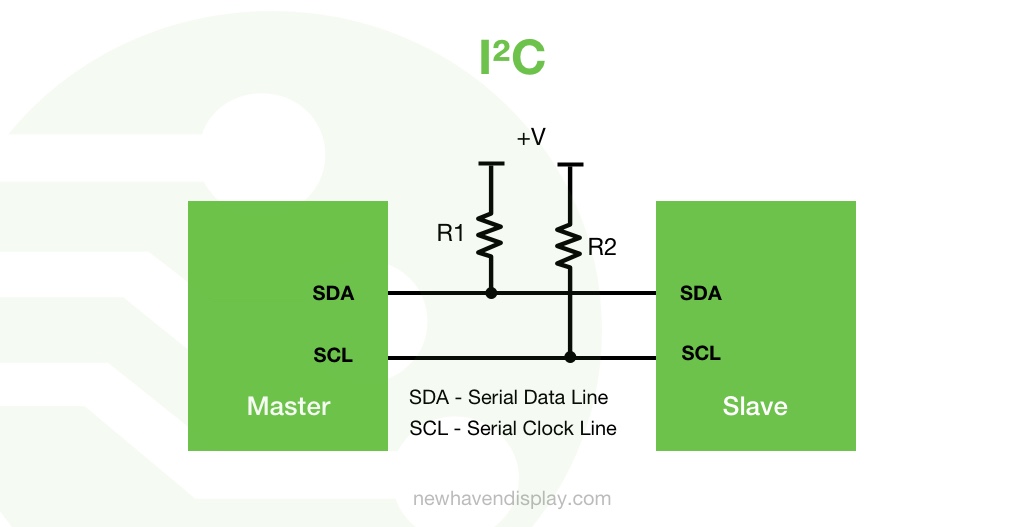
Devices on the I2C bus can either be a master or a slave:
- Master (controller): Initiates and controls data transfer on the bus.
- Slave (peripheral): Responds to the master.
The terms "master" and "slave" have been historically used to describe device roles on the I2C bus, but they have been replaced mainly by "controller" and "peripheral" in many contexts.
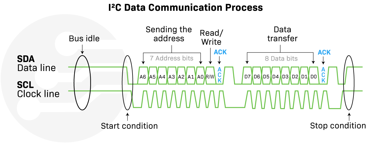
I2C Data Communication Process
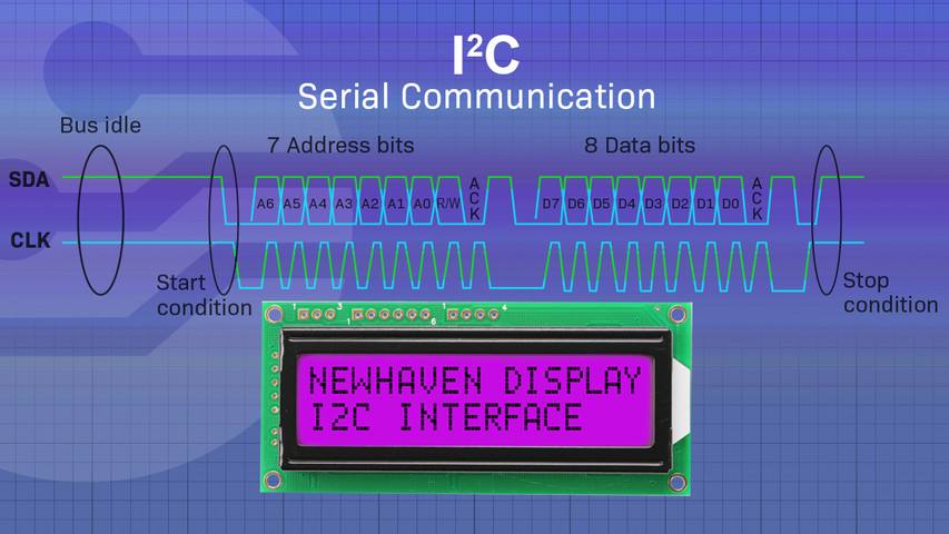
- Bus idle (bus free) condition:
- Before any communication begins, both the SDA (Serial Data Line) and SCL (Serial Clock Line) remain high, indicating the bus is idle.
- Start condition:
- Initiated by the master, a start condition occurs when the SDA line goes from high to low while the SCL line is high. This signals all slave devices that communication is about to start.
- Sending the address:
- The master device sends a 7-bit address to the slave it wants to communicate with. This is followed by an 8th bit, the Read/Write (R/W) bit, which indicates the operation's direction:
0for write and1for read. - This combined 8-bit sequence is called the address frame.
- In the special case of 10-bit addresses, the master sends 2 bytes. The first byte leads with 11110, followed by bits 9 and 8 of the 10-bit address, followed by the R/W bit. The second byte will contain bits 7-0 of the 10-bit address.
- The master device sends a 7-bit address to the slave it wants to communicate with. This is followed by an 8th bit, the Read/Write (R/W) bit, which indicates the operation's direction:
- Acknowledgment (ACK) bit:
- After the address and R/W bits are sent, the master releases the SDA line. The addressed slave device pulls the SDA line low (acknowledgment bit) to acknowledge that it has successfully received its address and is ready for communication.
- Data transfer:
- For a write operation, the master sends a byte of data to the slave. The slave acknowledges receipt by pulling the SDA line low for one clock pulse.
- For a read operation, the slave sends a byte of data to the master. The master acknowledges receipt but will release the SDA line (a NACK or no acknowledgment) after the last byte during a read operation, signaling the slave to stop sending data.
- Stop condition:
- To end a communication session, the master generates a stop condition by transitioning the SDA line from low to high while the SCL line is high. After the stop condition, the bus returns to the idle state.
- The master can also generate a repeated start condition to keep control of the bus for another read or write operation. This is often used in more complex operations, such as changing the data direction without releasing the bus.
Learn more: What is baud rate
Addressing Multiple Slaves
If there are multiple slave devices, the master communicates with each using their unique addresses. Only the slave with the matching address responds and communicates, while the others ignore the messages.
Clock Stretching
A slave can hold down the SCL line (a process known as clock stretching) if it needs more time to process an instruction or fetch data. The master must wait to proceed until the SCL is released.
Bus Arbitration (For Multi-Master)
Arbitration is the process of determining which master device gets control of the bus when multiple masters try to start communication simultaneously or within a close timeframe. I2C supports multiple masters, meaning more than one master can attempt to control the bus at a given time without corrupting the message.
I2C Arbitration Procedure:
- When a master starts a transmission, it assumes it has control of the bus.
- As it sends the address and data bits, it checks the SDA line after writing each bit. If it writes a
0and reads back a1, it knows another master has control and backs off, thus losing the arbitration. - The master that lost the arbitration stops transmitting immediately and waits for the SCL (Serial Clock) line to go HIGH, indicating the end of the current transfer, before trying again.
With efficient data transfer using only two wires, I2C has become a popular serial communication interface for systems seeking reliable and cost-effective communication.
Learn more: Example code for implementing I2C on a 16x2 COG LCD
Advantages of I2C:
- Simplicity: Requires only two wires, regardless of how many devices are connected.
- Flexibility: Supports multiple masters and slaves.
- Power efficiency: I2C peripherals can be powered down when not in use without affecting the bus.
- Built-in addressing: Each device on the bus has a unique address.
- Widely supported: Many microcontrollers and peripheral devices come with I2C hardware interfaces built-in, making integration easier.
- Flexible speed modes: I2C supports several speed modes.
Disadvantages of I2C:
- Speed limitations: Typically slower than other protocols like SPI.
- Distance limitations: I2C is designed for short distances. For longer distances, signal integrity and noise can become problematic.
- Complexity with large networks: As more devices are added, addressing can become complicated.
- No error checking: Lacks a built-in error-checking mechanism.
- Single-ended: No differential signaling, which could improve noise immunity.
I2C vs. Other Serial Communication Protocols
When choosing a serial communication protocol for your project, it is important to consider the specific needs of your application. While I2C is a popular choice, there are other protocols available, such as SPI, RS-232, CAN, and UART. Each protocol has its own advantages and disadvantages, so it is important to weigh the pros and cons before making a decision.
I2C vs. SPI (Serial Peripheral Interface):
- Wires: SPI requires more wires: SCLK (Serial Clock), MOSI (Master Out Slave In), MISO (Master In Slave Out), and a unique SS (Slave Select) for each device. In contrast, I2C only requires SDA and SCL.
- Speed: SPI can be faster than I2C as there is no address phase in data transmission.
- Flexibility: While I2C supports multi-master configuration natively, SPI doesn't.
I2C vs. UART (Universal Asynchronous Receiver-Transmitter):
- Protocol Complexity: UART is simpler as it only involves two devices talking to each other, using two lines (TX and RX). I2C can connect multiple devices using just two lines.
- Synchronization: UART is asynchronous (no clock line), while I2C is synchronous (requires a clock line).
I2C vs. CAN (Controller Area Network):
- Use Case: CAN is designed for vehicles and industrial systems where reliability under noisy conditions is crucial. I2C is more for short-distance, on-board communication between ICs.
- Reliability: CAN has built-in error-checking and correction mechanisms, while I2C does not.
I2C vs. RS232:
- RS232 Uses 3 wires and only supports two devices (one transmitter and one receiver), while I2C supports several devices with only 2 wires.
- RS-232 is suitable for long-distance communication.
| Protocol | Number of wires | Speed | Complexity | Power consumption | Common applications |
|---|---|---|---|---|---|
| I2C | 2 | Slow | Medium | Low | Embedded systems, sensors, displays, actuators, peripherals. |
| SPI | 4 | Fast | Medium | Medium | High-speed communication, memory chips. |
| UART | 2 | Slow | Low | Low | Asynchronous communication, serial communication over long distances. |
| CAN | 2 | Fast | Medium | Medium | Automotive and industrial applications. |
| RS-232 | 3 | Slow | Medium | Medium | Computers, printers, modems. |
Conclusion
I2C is an indispensable communication protocol with decades of proven efficacy in the electronics world. Its simplicity, combined with its capability to connect multiple devices using just two lines, makes it a popular choice for many applications. However, like any protocol, it has its limitations and is not ideal for all scenarios. When designing a system, one should evaluate the specific needs of the application and choose the communication protocol that aligns best with those needs.
Latest Blog Posts
-
US2066 Tutorial: Character Slim OLED with Arduino
If you are interested in getting started with character OLED displays using the US2066 controller …Jul 18th 2024 -
Passive Matrix vs Active Matrix - A Beginner's Guide
Have you ever wondered how display screens are able to produce sharp images and vibrant colors? T …May 30th 2024 -
How to Display Images on a TFT LCD
TFT LCDs, or thin-film transistor liquid-crystal displays, are a type of LCD commonly used in var …Apr 2nd 2024

