
How to Connect LCD to Arduino
The LCD (Liquid Crystal Display) is a commonly used display for Arduino projects, as it provides a simple way to output information to the user such as text and basic characters. It is a useful display for beginners and experienced users alike and is typically one of the first displays people use when they start using an Arduino board.
This tutorial will show you how to connect and interact between a 16x2 LCD Character Display and an Arduino UNO board using serial communication.
The principles in this tutorial can be applied to other LCD displays and other development boards as well. Let's get started!
LCD - Arduino Tutorial - Table of Contents
- Hardware and tools needed
- LCD pinout
- Arduino pinout
- Circuit - connection diagram and schematic for SPI communication
- Example code using SPI interface
- Circuit - connection diagram and schematic for RS232 TTL communication
- Hello World! example code using RS232 TTL interface
- Troubleshooting Your LCD - Arduino Project
- Additional resources
Hardware and Tools Needed
LCDs come in various sizes and configurations, but the most commonly used is the 16x2 LCD. It has 2 rows that can fit 16 characters per row.
We will be using the 16x2 Newhaven display part number NHD-0216K3Z-NSW-BBW-V3, which has a built-in PIC16F690 microcontroller. This LCD supports three serial interfaces: I2C, SPI, and RS-232 (TTL). This article will focus on the SPI and RS-232 interfaces and provide code examples for both.
This display is available for purchase here. The datasheet and product specs can be viewed or downloaded here.
Please note that using the SPI interface requires soldering a resistor to the display, whereas the RS-232 TTL interface does not. Therefore, if you prefer to follow this tutorial without soldering the resistor, you can follow the RS-232 TTL interface instructions and code example section.
Things you will need to connect Arduino to an LCD
- LCD 16x2
- Single row pin header connector
- Arduino UNO
- breadboard
- Jumper wires
- Solder and soldering iron
- USB A male to B Male Cable (printer cable)
- Arduino IDE
- 0 ohm resistor (optional - for SPI communication only)
We suggest reading our blog article How to Protect Electronics from ESD before diving into this tutorial, especially If you are a beginner with electronics.
16x2 LCD Pinout
The Newhaven 16x2 character LCD offers a simple way to interact with the Arduino UNO board using serial communication. The pins on the P1 port are specifically designed for RS232 TTL serial communication, and the pins on the P2 port are for serial I2C and SPI communication.
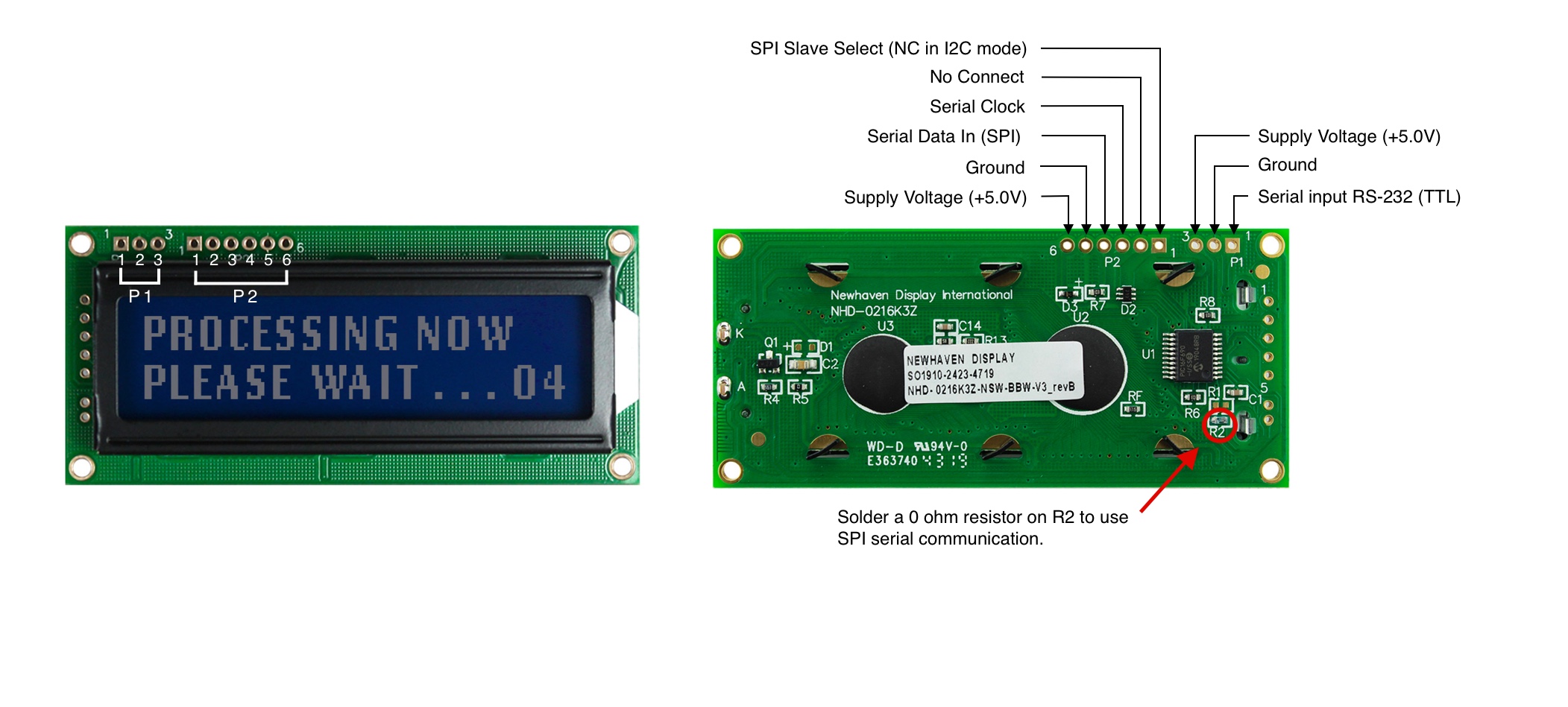
P1 Pin Description - RS232 TTL Communication
| Pin No. | Symbol | Function Description |
|---|---|---|
| 1 | RX | RS-232 (TTL) Serial input |
| 2 | V SS | Ground |
| 3 | V DD | Supply Voltage (+5.0V) |
P2 Pin Description - SPI and I2C Communication
| Pin No. | Symbol | Function Description |
|---|---|---|
| 1 | SPISS | SPI Slave Select (NC in I2C mode) |
| 2 | SDO | No Connect |
| 3 | SCK/SCL | Serial Clock |
| 4 | SDI/SDA | Serial Data In (SPI) / Serial Data (I2C) |
| 5 | V SS | Ground |
| 6 | V DD | Supply Voltage (+5.0V) |
The complete LCD pinout specification can be viewed here.
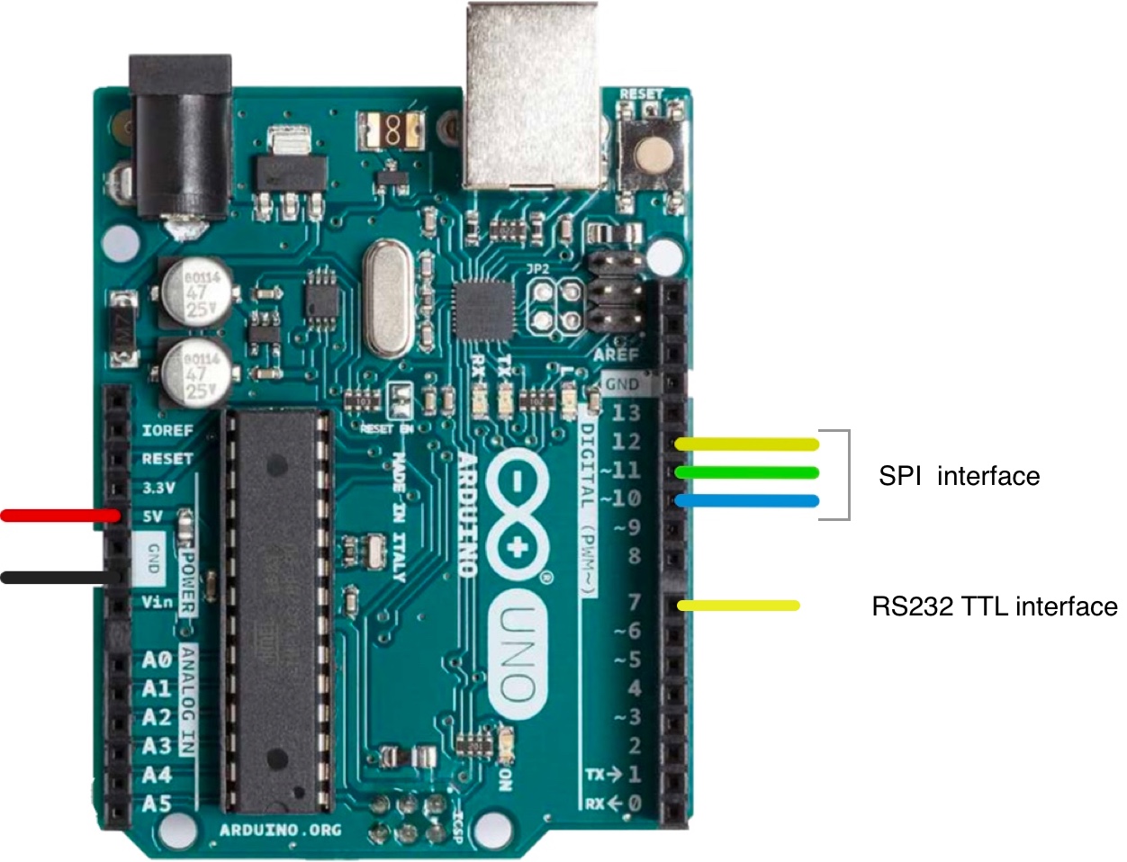
Arduino Pinout
The Arduino UNO board has 20 input/output pins, including 14 digital pins and 6 analog pins, and for this project, we will use the 5V and GND pins from the power signals, pins 10, 11, and 12 for SPI or I2C, and pin 7 for RS232 TTL.
The complete Arduino UNO pinout schematic can be viewed here.
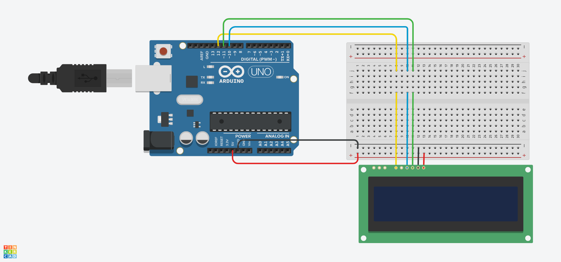
Circuit - Connection Diagram and Schematic for SPI Communication
The Serial Peripheral Interface (SPI) is a synchronous serial communication bus used for short-distance, high-speed communication between multiple devices. The connection circuit for SPI communication between the Arduino (master device) and the LCD (slave device) uses five wires to communicate as described in the table below:
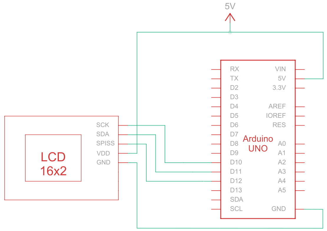
| Arduino | LCD | Connection Type |
|---|---|---|
| 5V Pin | Pin 6: V DD | Power |
| Ground Pin | Pin 5: Ground | Ground |
| Pin 10: Slave Select | Pin 3: SCK/SCL | Serial Clock |
| Pin 11: MISO | Pin 4: Serial Data In (SPI) / Serial Data (I2C) | Serial Data In |
| Pin 12: MOSI | Pin 1: SPISS | SPI Slave Select |
Note:
Enabling SPI requires R1 to be open and R2 to be shortened as specified in the
datasheet. Also, before starting, ensure the Arduino is powered off while wiring up the circuit.
SPI Wiring circuit
SPI Wiring Schematic
Arduino - LCD Example Code Using SPI interface
The following code examples demonstrate how to use serial communication between Arduino and a 16x2 character LCD using the SPI interface. You will find helpful comments in the code examples, but let's break down some of the functions below:
- The
SPI_Out()function sends commands and data to the LCD display through SPI. It does this by iterating through the 8 bits of the input byte and sending each bit's value to the LCD display. - The
Set_Pins()function configures the SPI pins as output pins. - The
Set_Contrast()function sets the contrast of the LCD display. - The
Set_Backlight()function sets the backlight of the LCD display. - The
Clear_Display()function clears the LCD screen. - The
Set_Cursor()function enables or disables the blinking cursor on the LCD display, depending on the input parameter. - The
setup()function is the main function and is executed once when the Arduino starts. It is used to initialize the settings, variables and any run any other necessary functions and configurations for the project. - The
loop()function runs in a continuous loop for the entire duration that the Arduino board is powered on. In some examples below, this function is empty and does nothing because we just need to run some functions once.
Arduino - LCD code examples using SPI:
- Hello world!
- Display text on the first and second row
- Display long text
- Display text with a blinking cursor
- Cursor + autoscroll text
- Autoscroll
- Contrast
- Backlight
- Characters/font tables
You can adapt and expand the code examples to suit your specific Arduino-based project requirements.
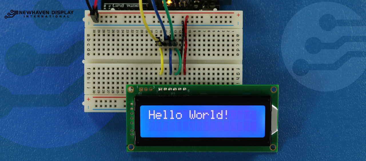
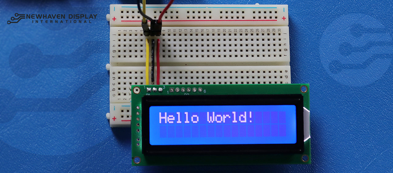
Hello world!
The following code example displays "Hello Word!" on the LCD.
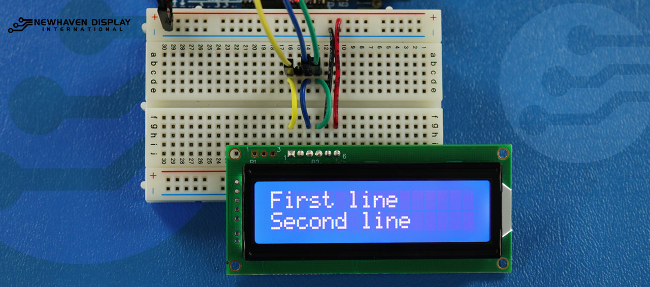
Display text on the first and second row
This code will show the text "First Line" in the first row and "Second Line" in the second row.
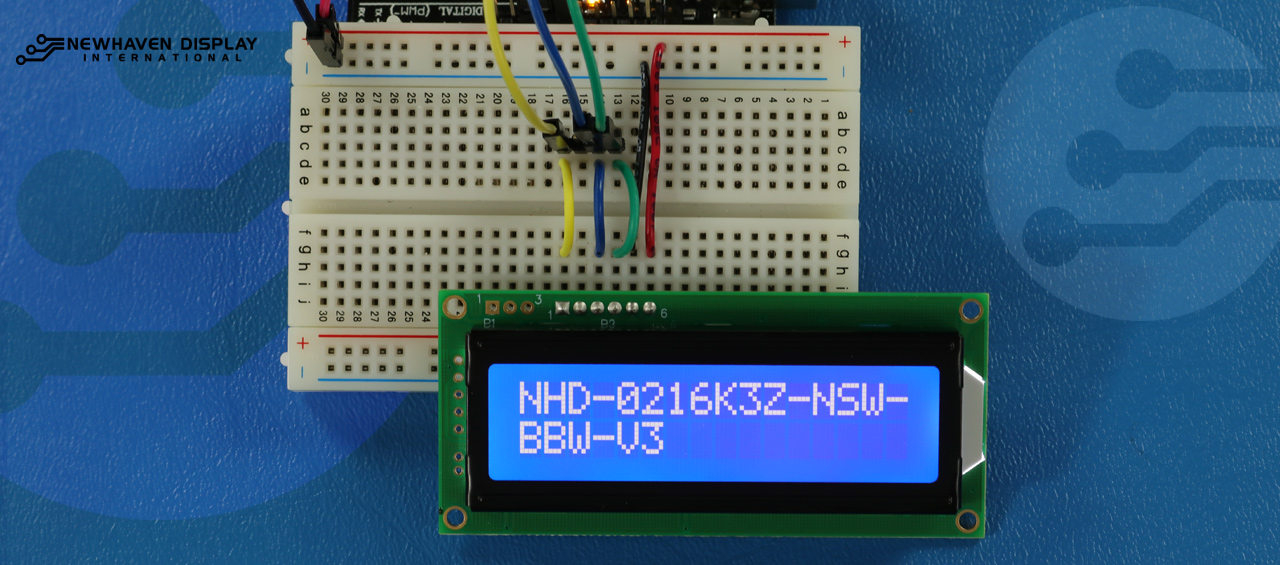
Display long text
This code displays text that extends to the second row. For this example, we will display the text "NHD-0216K3Z-NSW-BBW-V3".
Blink - Display text with blinking cursor
This code displays text with a blinking cursor. For this example, we will display the text "NHD-0216K3Z-NSW-BBW-V3".
Cursor + autoscroll text
This code first displays text with the cursor on and then initializes autoscrolling to the right.
Autoscroll text
This code autoscrolls the text "NHD-0216K3Z-NSW-BBW-V3".
Adjusting the LCD contrast
This code displays the text "NHD-0216K3Z-NSW-BBW-V3" while changing the contrast.
How to use the LCD backlight
There are different methods for controlling or adjusting the backlight of the LCD. Two of the most common ways of controlling or adjusting the LCD backlight are via a command or a potentiometer.
For our serial displays like the NHD-0216K3Z-NSW-BBW-V3, the backlight can be controlled via a command. The
Backlight_loop() function sets the backlight brightness value from highest to lowest and then from lowest to highest in a constant loop.
The code below displays the text "NHD-0216K3Z-NSW-BBW-V3" while changing the backlight intensity.
Characters/font tables
This code displays characters from the font table that is included in the LCD.
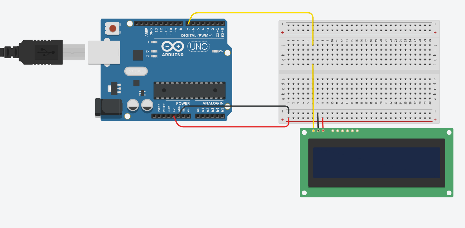
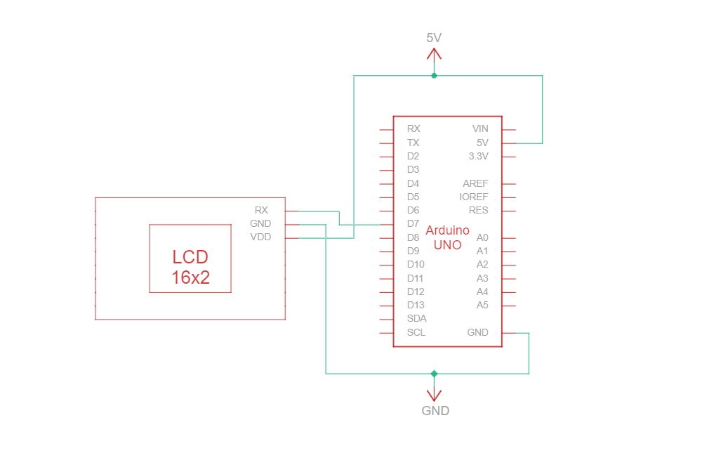
Circuit - Connection Diagram and Schematic for RS232 TTL Communication
RS232 TTL is a serial communication protocol that uses RS232-type specs but with TTL logic levels (0V to Vcc, typically 3.3V or 5V). The RS232 TTL connection circuit between Arduino and the 16-character Newhaven display uses only three wires:
| Arduino | LCD | Connection Type |
|---|---|---|
| 5V Pin | Pin 3: V DD | Power |
| Ground Pin | Pin 2: Ground | Ground |
| Pin 7: Digital I/O pin | Pin 1: RX | RS-232 (TTL) Serial input port |
Note:
R1 and R2 on the display must be open to enable RS232 TTL as specified in the
datasheet.
RS232 TTL Wiring circuit
RS232 TTL Wiring Schematic
We have created a detailed beginner-friendly tutorial on Instructables for RS232 TTL communication. The tutorial includes all the necessary steps to complete this project. Check it out here: www.instructables.com/Arduino-LCD-Tutorial/
Arduino - LCD Hello World! Code Example Using serial RS232 TTL communication
The following code example displays "Hello Word!" on the LCD using RS232 TTL communication.
Troubleshooting Your LCD - Arduino Project
Below we will discuss some common steps to take when encountering issues or problems with your Arduino - LCD project.
- Check wiring connections: The most common issue when connecting an LCD to an Arduino is incorrect wiring. Check your wiring connections against the provided pinout diagram and circuit to ensure proper connectivity. Additionally, keep in mind that the NHD-0216K3Z-NSW-BBW-V3 display can be configured to work with SPI, I2C, and RS232 TTL interfaces. A 0 ohm resistor must be soldered onto the R2 section in the PCB to work with the SPI interface.
- Inspect components: Look for any visible signs of damage on the Arduino, LCD, or connecting wires.
- Verify the code: Ensure the uploaded code on your Arduino is correct and free from errors.
- Check the power supply: Ensure that your power source is sufficient to power both the Arduino and the LCD.
- Test with a known-good LCD: If you are still experiencing issues, try connecting a different, known-good LCD to your Arduino. This will help you determine if the problem is with the LCD or the Arduino board itself.
- Adjust contrast: If you are having trouble seeing the displayed text on the LCD, try adjusting the contrast using the software function
Set_Contrast(), which is described above. Different lighting conditions might require different contrast settings for optimal visibility. - Check the Arduino IDE version: Ensure that you are using the latest version the Arduino IDE. Outdated versions might contain bugs or be incompatible with your project.
- Test individual features: If you are having issues with specific features like scrolling or contrast control, try running simpler code like the "Hello World!" example to isolate the problem. This can help you determine if the issue is related to the code or the hardware.
- Seek help from the community: If you are unable to resolve the issue after following the above troubleshooting steps, consider seeking help from the online community. Online forums, such as the Newhaven Display Support Forum, the Arduino Stack Exchange, or the Arduino.cc forum, are excellent resources for getting assistance from experienced users.
By following these troubleshooting steps, you should be able to diagnose and resolve most issues related to connecting an LCD to an Arduino board. Remember, patience and attention to detail are key when troubleshooting electronics projects.
Additional Resources
- Arduino UNO official website.
- LCD 16x2 product description.
- LCD 16x2 product datasheet and specs.
- Beginner-friendly Arduino-LCD Instructables Tutorial
- Character LCD Support Forum.
- Read our beginner's guide to prototyping displays.
- Character LCD sample code.
- Learn how to protect electronics from ESD.
- Learn about the types of LCDs.
- Learn about LCD modes.

Senaste blogginläggen
-

Understanding Display Viewing Angles
Have you ever found it difficult to read an ATM screen from the side or noticed how a display appear …Feb 4th 2025 -

OEM vs ODM Manufacturing - Differences, Benefits, and Limitations
When outsourcing manufacturing, two terms come across: OEM (Original Equipment Manufacturer) and …Nov 26th 2024 -

Raspberry Pi Custom HDMI TFT LCD Timings
Setting up custom timing for HDMI TFTs and Touch HDMI Displays on Raspberry Pi can significant …Oct 29th 2024