

-
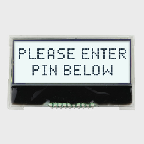

16x2 Chip on Glass Character LCD / 3,3 V FSTN(+) / białe podświetlenie z interfejsem szeregowym
Model: NHD-C0216CZ-FSW-FBW-3V3
Zarys: 41,4 mm x 24,3 mm
$12.75W MAGAZYNIE -

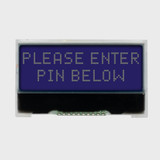
16x2 Chip on Glass Character LCD / 3,3 V STN (-) Niebieskie / białe podświetlenie z interfejsem szeregowym
Model: NHD-C0216CZ-NSW-BBW-3V3
Zarys: 41,4 mm x 24,3 mm
$12.69W MAGAZYNIE -
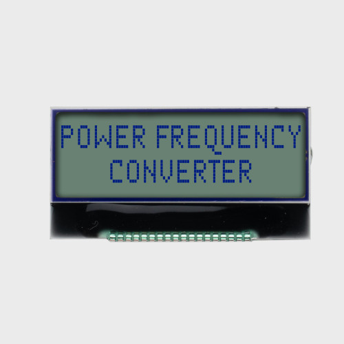
16x2 Chip on Glass Character LCD / 5,0 V STN (+) Szary / Bez podświetlenia z interfejsem SPI
Model: NHD-C0216BA-FN-GBW
Zarys: 49,4 mm x 25,3 mm
$8.90W MAGAZYNIE -
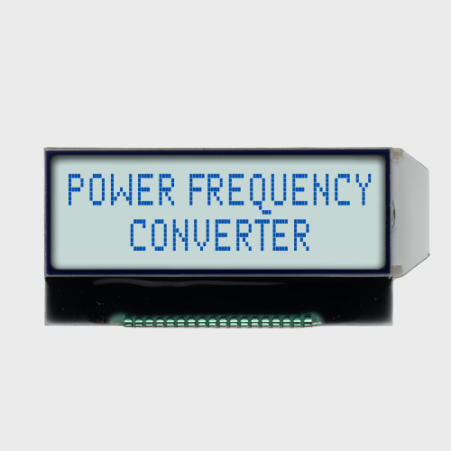

16x2 Chip on Glass Character LCD / 5,0 V STN (+) Szary / Białe podświetlenie z interfejsem SPI
Model: NHD-C0216BA-FSW-GBW
Zarys: 54,55 mm x 25,3 mm
$9.30W MAGAZYNIE -
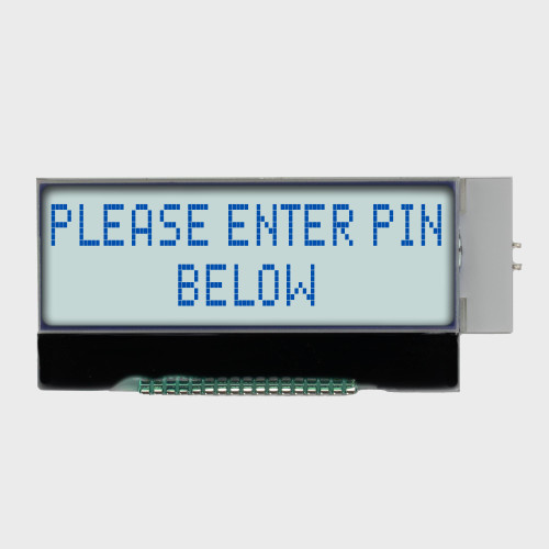

16x2 Chip na szkle LCD znakowy / 3,0 V STN (+) szary / białe podświetlenie
Model: NHD-C0216CU-FSW-GBW-3V3
Zarys: 56,0 mm x 25,3 mm
$12.16W MAGAZYNIE -


Wyświetlacz znakowy LCD typu „chip on glass” o rozdzielczości 16x2 / 3,0 V FSTN(+) / białe podświetlenie z interfejsem I2C
Model: NHD-C0216CiZ-FSW-FBW-3V3
Zarys: 56,8 mm x 26,2 mm
$13.23W MAGAZYNIE -



20x2 Chip on Glass Character LCD / 3.3V FSTN-Positive / RGB Backlight with I2C Interface + Mounting Holes
Model: NHD-C0220BiZ-FS(RGB)-FBW-3VM
Zarys: 71,6 mm x 37,6 mm
$14.46W MAGAZYNIE -


20x2 Chip on Glass Character LCD / 3.3V FSTN-Positive / White Backlight with I2C Interface + Mounting Holes
Model: NHD-C0220BiZ-FSW-FBW-3V3M
Zarys: 71,6 mm x 37,6 mm
$12.73W MAGAZYNIE -


20x2 Chip on Glass Character LCD / 3.3V FSTN-Positive 12:00 view / White Backlight
Model: NHD-C0220BA-FSW-FTW-3V3
Zarys: 74,5 mm x 25,0 mm
$12.28W MAGAZYNIE -


20x2 Chip on Glass Character LCD / 5.0V FSTN-Positive 12:00 View / White Backlight
Model: NHD-C0220BA-FSW-FTW
Zarys: 74,5 mm x 25,0 mm
$12.28W MAGAZYNIE -


20x4 Character COG LCD / 3.3V STN Negative Blue with White Backlight / 5.2mm Character Height
Model: NHD-C0420AZ-NSW-BBW-3V3
Outline: 69.0mm x 38.0mm
$13.17W MAGAZYNIE -


20x4 Character COG LCD / 3.3V FSTN+ with White Backlight / 5.2mm Character Height
Model: NHD-C0420AZ-FSW-FBW-3V3
Outline: 69.0mm x 38.0mm
$13.56W MAGAZYNIE
Wyświetlacze LCD typu „Chip on Glass” (COG)
Slim, Cost-Effective Character and Graphic LCDs
Optimize space and efficiency with our COG LCD displays. Available in both character and graphic formats, these displays feature driver and controller circuitry bonded directly to the glass, eliminating the need for a PCB. The result is a slimmer, more economical design that offers outstanding reliability and flexibility for custom applications.
How to Choose a Chip-On-Glass (COG) LCD
Here are six decisions to help narrow our wide selection of displays to the COG LCD that's right for your product: format, interface, supply voltage, connection, display mode and backlight, and operating environment. Work through them in order, and you'll land on a short list of in-stock modules ready to incorporate into your design.
01 · FORMAT
Character or Graphic COG
Text in a fixed grid, or control of every pixel?
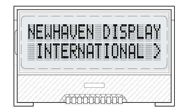
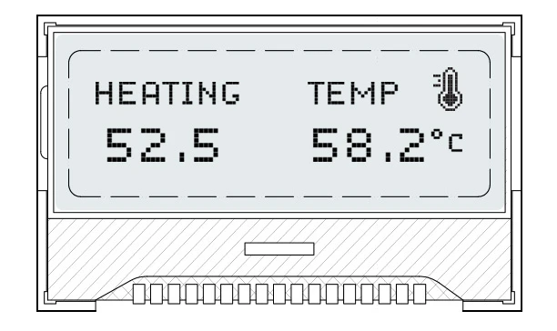
COG LCDs come in both formats. Character COGs display text in 2×16, 2×20, and 4×20 grids with a built-in font, so your firmware simply sends characters. Graphic COGs range from 128×32 to 240×64, plus a square 128×128, and give you every pixel for icons, custom fonts, and bar graphs. Start with the most complex screen your product needs, then check the outline against your enclosure. Our smallest 2×16 COG measures just 26.8×26.2mm.
 Character COG
| Options | Controllers | Best For |
|---|---|---|
|
|
Text readouts, menus, status messages |
 Graphic COG
| Options | Controllers | Best For |
|---|---|---|
|
|
Icons, custom fonts, bar graphs, simple UIs |
02 · INTERFACE
Built-in Interface
How will the display talk to your microcontroller?
With the controller bonded directly to the glass, every COG is ready to connect to your microcontroller. SPI is the most common choice across our COGs and keeps wiring to a handful of pins. I2C cuts it to two signal lines and is available on select 2×16, 2×20, and 4×20 character models and our 160×100 graphic. Parallel is there when you have pins to spare and want the fastest updates, and many models support more than one option.
 SPI
3/4-Wire
Synchronous
Most graphic COG and pin-constrained designs
Usually write-only on graphic models. Set aside MCU RAM for a frame buffer
 I²C
2-Wire
Addressable
Character COG sharing a bus with sensors
Slowest refresh. Needs pull-up resistors on SDA/SCL
 Równolegle
8-Bit
6800/8080
Fastest updates when I/O pins are available
Uses the most pins, check your pin budget
03 · POWER
Supply Voltage and Power
3.3V, 5V, or battery-powered?
Most of our COGs run on 3.0-3.3V, with select character models at 5V, so they fit neatly into modern low-voltage designs. With no PCB and a controller that generates the LCD drive voltage on-chip, COGs draw very little current, especially reflective models with no backlight. Many need a few external capacitors for that on-chip voltage booster, so build the datasheet's reference circuit into your board from the start.

04 · CONNECTION
Pins, Flex Cable, & Mounting Holes
How will the display attach to your board?
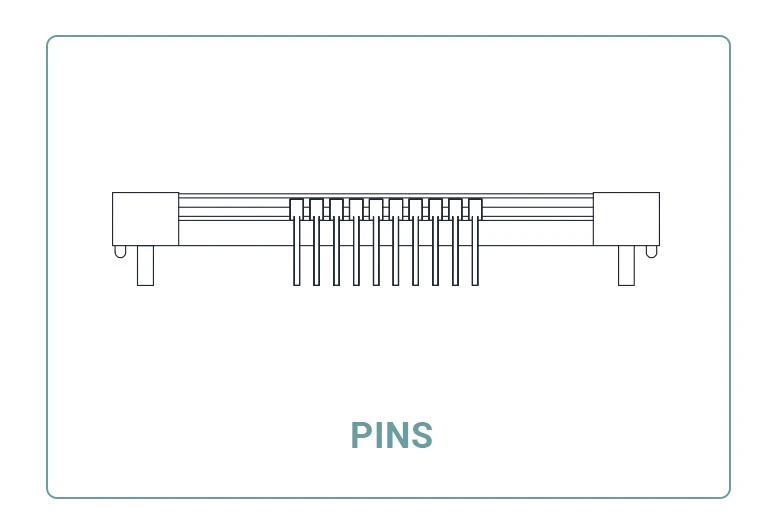
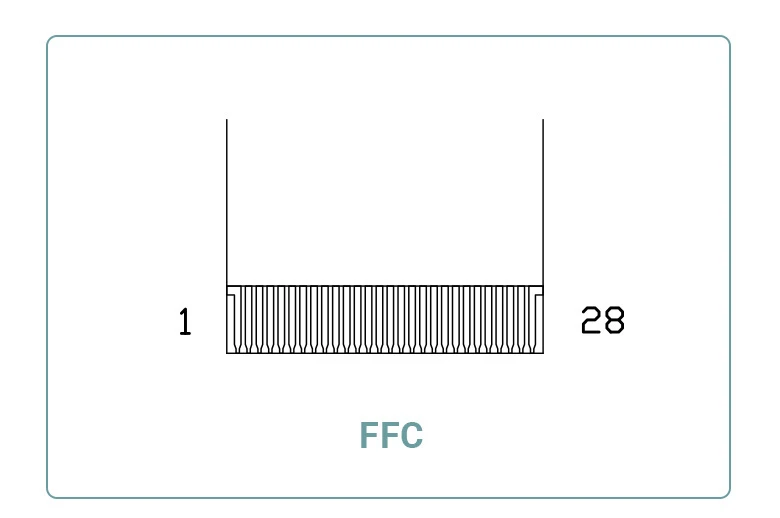
COGs connect in one of two ways. Pin versions have metal pins attached to the glass, typically at 1.27–2.0mm pitch, that solder straight into your PCB for a rigid assembly. FFC versions use a 0.5mm-pitch flex cable and connector, giving you freedom to place the display away from the board. For a sturdier mount, choose a model with mounting holes, and for prototyping, our COG breakout board brings the pins out to a standard through-hole header.
05 · DISPLAY MODE
Display Mode, Type, & Backlight
Bright sunlight, dim rooms, or both?
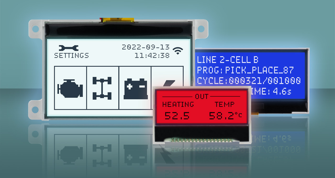
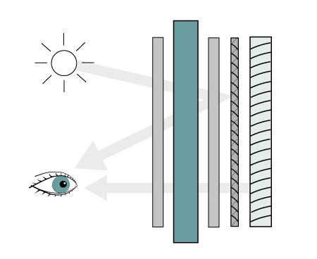
Reflective COGs have no backlight, are as thin as 2mm, and read best in bright light with the lowest power draw. Transflective models, the most common in our lineup, add a backlight for dim conditions while staying readable in bright light. Transmissive negative-mode displays show white characters on blue for a bold low-light look. Backlights come in white, blue, red, and RGB, and FSTN models deliver the crispest, most neutral contrast.
 Reflective
 Transflective
 Transmissive (Negative)
06 · ENVIRONMENT
Operating Temperature and Viewing Angle
How cold will it get, and where will users stand?
Standard COGs are rated for -20°C to 70°C. For colder environments, our 128×64 COGs with a built-in 12V heater operate down to -40°C. Like all passive LCDs, COGs are optimized for peak contrast from one direction. Most are 6:00, best when the viewer is below looking up, with select 12:00 models for displays viewed from above.

Często zadawane pytania
A COG LCD has its controller and driver IC bonded directly to the display glass instead of mounted on a separate PCB. Removing the board makes the display thinner, lighter, and more economical, while keeping a standard interface like SPI, I2C, or parallel. We offer COGs in both character and graphic formats.
COB (Chip on Board) modules mount the controller on a PCB with a pin header and mounting holes, typically run on 5V, and are rugged and easy to wire on the bench. COG displays skip the PCB, so they're thinner (as slim as 2mm), lower cost, and suited to 3.0-3.3V designs, but they need a little more care in mounting and board design. Prototyping fast? Start with COB. Tight on depth or cost? Go COG.
Usually a few. Many COG controllers generate the LCD drive voltage with an on-chip booster that needs external capacitors, and backlit models typically need a current-limiting resistor for the LED. The datasheet for each part includes a reference circuit, so copy it into your schematic before you lay out the board.
Support the glass evenly and keep pressure off the edges and the exposed controller chip. Avoid sharp bends in flex cables, follow ESD precautions during assembly, and use mounting holes, a bezel, or adhesive rather than relying on the pins alone to hold the display. For prototyping, our breakout board protects the pins and gives you a standard header.
Yes. Our Support Center has Arduino examples and datasheets for our COG LCDs, including the 2×16 and 2×20 character models and the 128×32 graphic. Start from the example for your display's controller and get text on the screen before you write any application code.
Yes. Common changes include backlight color, cable and connector modifications, and pre-soldering COG displays to breakout boards. For higher volumes, we can build fully custom COG glass to your size, layout, and interface requirements. Start from the closest standard part and tell us what needs to change.