Wie man LCD an Arduino anschließt
19. Mai 2023
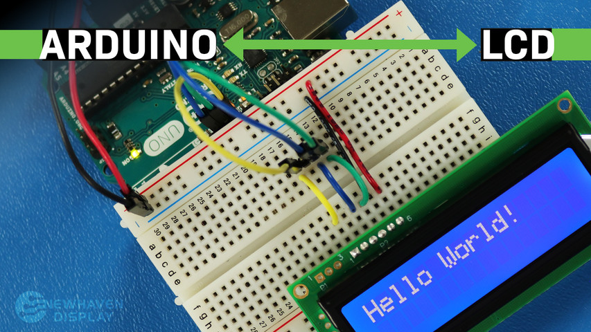
Das LCD (Liquid Crystal Display) ist ein häufig verwendetes Display für Arduino-Projekte, da es eine einfache Möglichkeit bietet, Informationen wie Text und einfache Zeichen an den Benutzer auszugeben. Es ist eine nützliche Anzeige für Anfänger und erfahrene Benutzer gleichermaßen und ist in der Regel eine der ersten Anzeigen, die Leute verwenden, wenn sie mit einem Arduino-Board beginnen.
This tutorial will show you how to connect and interact between a 16x2 LCD Character Display and an Arduino UNO board using serial communication.
The principles in this tutorial can be applied to other LCD displays and other development boards as well. Let's get started!
LCD - Arduino Tutorial - Inhaltsverzeichnis
- Benötigte Hardware und Werkzeuge
- LCD-Pinout
- Arduino-Pinbelegung
- Schaltung - Anschlussplan und Schaltplan für SPI-Kommunikation
- Beispielcode mit SPI-Schnittstelle
- Schaltung - Anschlussplan und Schaltplan für RS232 TTL Kommunikation
- Hello World! Beispielcode mit RS232 TTL Schnittstelle
- Fehlersuche für Ihr LCD - Arduino-Projekt
- Zusätzliche Ressourcen
Benötigte Hardware und Werkzeuge
LCDs gibt es in verschiedenen Größen und Konfigurationen, aber die am häufigsten verwendete ist die 16x2 LCD. Es hat 2 Zeilen, die 16 Zeichen pro Zeile aufnehmen können.
We will be using the 16x2 Newhaven display part number NHD-0216K3Z-NSW-BBW-V3, which has a built-in PIC16F690 microcontroller. This LCD supports three serial interfaces: I2C, SPI, and RS-232 (TTL). This article will focus on the SPI and RS-232 interfaces and provide code examples for both.
This display is available for purchase here. The datasheet and product specs can be viewed or downloaded here.
Please note that using the SPI interface requires soldering a resistor to the display, whereas the RS-232 TTL interface does not. Therefore, if you prefer to follow this tutorial without soldering the resistor, you can follow the RS-232 TTL interface instructions and code example section.
Was Sie benötigen, um den Arduino an ein LCD anzuschließen
- LCD 16x2
- Einreihiger Stiftleistenanschluss
- Arduino UNO
- Steckbrett
- Überbrückungsdrähte
- Lötzinn und Lötkolben
- USB A-Stecker auf B-Stecker Kabel (Druckerkabel)
- Arduino-IDE
- 0-Ohm-Widerstand (optional - nur für SPI-Kommunikation)
We suggest reading our blog article How to Protect Electronics from ESD before diving into this tutorial, especially If you are a beginner with electronics.
16x2 LCD Pinout
The Newhaven 16x2 character LCD offers a simple way to interact with the Arduino UNO board using serial communication. The pins on the P1 port are specifically designed for RS232 TTL serial communication, and the pins on the P2 port are for serial I2C and SPI communication.
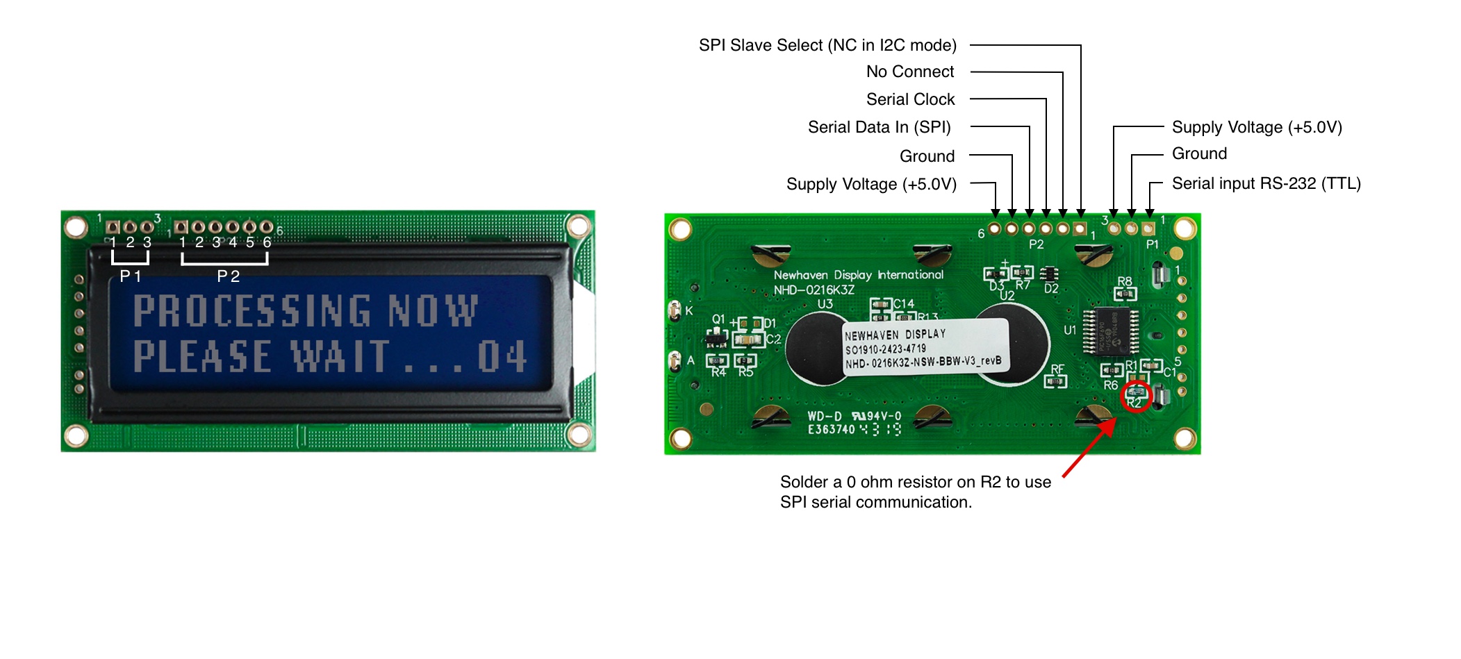
P1 Pin Beschreibung - RS232 TTL Kommunikation
| Stift Nr. | Symbol | Funktion Beschreibung |
|---|---|---|
| 1 | RX | RS-232 (TTL) Serieller Eingang |
| 2 | V SS | Boden |
| 3 | V DD | Versorgungsspannung (+5.0V) |
P2 Pin-Beschreibung - SPI- und I2C-Kommunikation
| Stift Nr. | Symbol | Funktion Beschreibung |
|---|---|---|
| 1 | SPISS | SPI Slave Select (NC im I2C-Modus) |
| 2 | SDO | Keine Verbindung |
| 3 | SCK/SCL | Serielle Uhr |
| 4 | SDI/SDA | Serieller Dateneingang (SPI) / Serielle Daten (I2C) |
| 5 | V SS | Boden |
| 6 | V DD | Versorgungsspannung (+5.0V) |
The complete LCD pinout specification can be viewed here.
Arduino-Pinout
Das Arduino UNO-Board hat 20 Eingangs-/Ausgangs-Pins, darunter 14 digitale Pins und 6 analoge Pins, und für dieses Projekt werden wir die 5V- und GND-Pins der Stromsignale, die Pins 10, 11 und 12 für SPI oder I2C und Pin 7 für RS232 TTL verwenden.
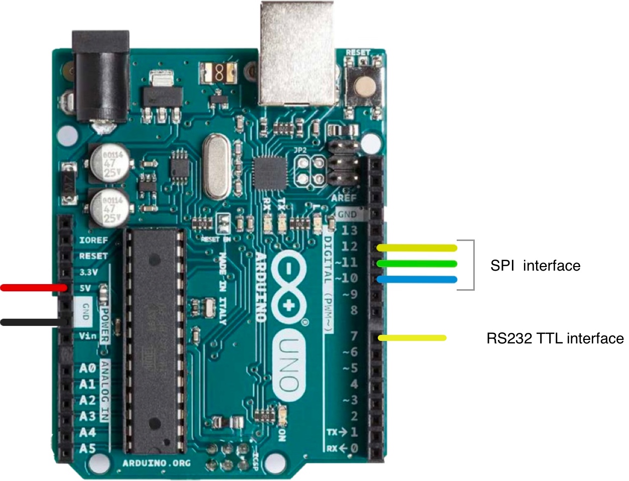
The complete Arduino UNO pinout schematic can be viewed here.
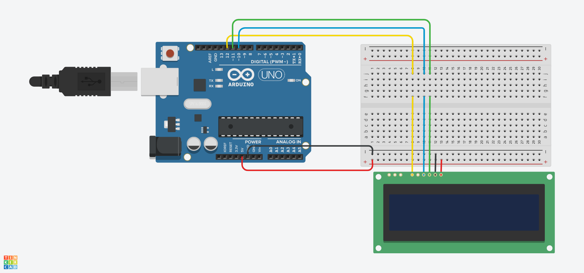
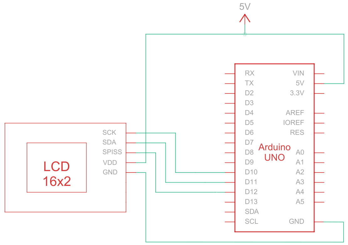
Schaltung - Anschlussdiagramm und Schaltplan für SPI-Kommunikation
Das Serial Peripheral Interface (SPI) ist ein synchroner serieller Kommunikationsbus, der für die Hochgeschwindigkeitskommunikation über kurze Entfernungen zwischen mehreren Geräten verwendet wird. Die Verbindungsschaltung für die SPI-Kommunikation zwischen dem Arduino (Master-Gerät) und dem LCD (Slave-Gerät) verwendet fünf Drähte zur Kommunikation, wie in der Tabelle unten beschrieben:
| Arduino | LCD | Verbindungstyp |
|---|---|---|
| 5V Stift | Pin 6: V DD | Strom |
| Erdungsstift | Pin 5: Masse | Boden |
| Pin 10: Slave-Auswahl | Stift 3: SCK/SCL | Serielle Uhr |
| Stift 11: MISO | Pin 4: Serieller Dateneingang (SPI) / Serielle Daten (I2C) | Serielle Daten Eingang |
| Stift 12: MOSI | Stift 1: SPISS | SPI-Slave-Auswahl |
Note:
Enabling SPI requires R1 to be open and R2 to be shortened as specified in the datasheet. Also, before starting, ensure the Arduino is powered off while wiring up the circuit.
SPI Verdrahtungsschaltung
SPI-Verdrahtungsschema
Arduino - LCD Beispielcode mit SPI Schnittstelle
Die folgenden Code-Beispiele zeigen, wie die serielle Kommunikation zwischen Arduino und einem 16x2-Zeichen-LCD unter Verwendung der SPI-Schnittstelle funktioniert. Sie finden hilfreiche Kommentare in den Codebeispielen, aber lassen Sie uns einige der Funktionen unten aufschlüsseln:
- Die
SPI_Out()Funktion sendet Befehle und Daten über SPI an das LCD-Display. Dazu durchläuft sie die 8 Bits des Eingangsbytes und sendet den Wert jedes Bits an das LCD-Display. - Die
Set_Pins()Funktion konfiguriert die SPI-Pins als Ausgangspins. - Die
Kontrast_einstellen()wird der Kontrast des LCD-Displays eingestellt. - Die
Hintergrundbeleuchtung einstellen()wird die Hintergrundbeleuchtung des LCD-Displays eingestellt. - Die
Clear_Display()Funktion löscht den LCD-Bildschirm. - Die
Set_Cursor()aktiviert oder deaktiviert den blinkenden Cursor auf dem LCD-Display, je nach Eingabeparameter. - Die
setup()Funktion ist die Hauptfunktion und wird einmal beim Start des Arduinos ausgeführt. Sie wird verwendet, um die Einstellungen und Variablen zu initialisieren und alle anderen notwendigen Funktionen und Konfigurationen für das Projekt auszuführen. - Die
Schleife()function runs in a continuous loop for the entire duration that the Arduino board is powered on. In some examples below, this function is empty and does nothing because we just need to run some functions once.
Arduino - LCD-Codebeispiele mit SPI:
- Hallo Welt!
- Anzeige von Text in der ersten und zweiten Zeile
- Langtext anzeigen
- Text mit blinkendem Cursor anzeigen
- Cursor + Autoscroll-Text
- Autoscroll
- Kontrast
- Hintergrundbeleuchtung
- Zeichen/Schrifttabellen
Sie können die Code-Beispiele anpassen und erweitern, um sie an Ihre spezifischen Arduino-basierten Projektanforderungen anzupassen.
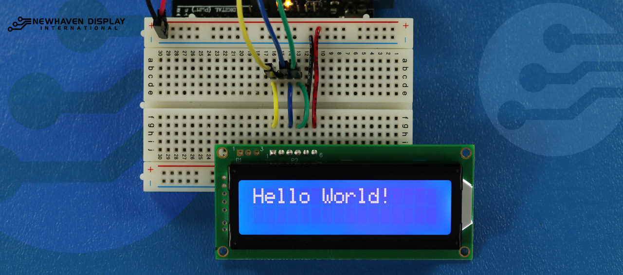
Hallo Welt!
The following code example displays "Hello Word!" on the LCD.
/*  SPI Wiring Reference for: NHD-0216K3Z-NSW-BBW-V3
  ---------------------------
  LCD         |   Arduino
  ---------------------------
  1(SPISS)  --> 12
  2(SDO)    --> No Connect
  3(SCK)    --> 10
  4(SDA)    --> 11
  5(VSS)    --> Ground
  6(VDD)    --> 5V
*/
/*****************************************************
   Arduino pin definition
  /*****************************************************/
#define SPISS_PIN   12
#define SDA_PIN     11
#define SCK_PIN     10
/*****************************************************
   SPI function to send command and data.
   For more information on SPI please visit our Support Center
  /*****************************************************/
void SPI_Out(unsigned char a) {
  digitalWrite(SPISS_PIN, LOW);
  for (int n = 0; n < 8; n++) {
    if ((a & 0x80) == 0x80) {
      digitalWrite(SDA_PIN, HIGH);
      delayMicroseconds(200);
    }
    else {
      digitalWrite(SDA_PIN, LOW);
    }
    delayMicroseconds(200);
    a = a << 1;
    digitalWrite(SCK_PIN, LOW);
    digitalWrite(SCK_PIN, HIGH);
    delayMicroseconds(200);
  }
  digitalWrite(SCK_PIN, HIGH);
  delayMicroseconds(200);
  digitalWrite(SPISS_PIN, HIGH);
}
/*****************************************************
   Set Arduino UNO IO ports as Output mode
  /*****************************************************/
void Set_Pins() {
  pinMode(SPISS_PIN, OUTPUT);
  pinMode(SCK_PIN, OUTPUT);
  pinMode(SDA_PIN, OUTPUT);
}
/*****************************************************
   Set LCD Contrast
  /*****************************************************/
void Set_Contrast() {
  SPI_Out(0xFE);              //prefix command
  SPI_Out(0x52);              //contrast command
  SPI_Out(0x28);              //set contrast value
  delayMicroseconds(500);
}
/*****************************************************
   Set LCD Backlight
  /*****************************************************/
void Set_Backlight() {
  SPI_Out(0xFE);             //prefix command
  SPI_Out(0x53);             //backlight command
  SPI_Out(0x08);             //set backlight value
  delayMicroseconds(100);
}
/*****************************************************
   Clear LCD
  /*****************************************************/
void Clear_Display() {
  SPI_Out(0xFE);             //prefix command
  SPI_Out(0x51);             //clear display command
  delayMicroseconds(1500);
}
/*****************************************************
   Set cursor
   Mode = 0 sets Blinking cursor off
   Mode = 1 sets Blinking cursor on
  /*****************************************************/
void Set_Cursor(int mode) {
  SPI_Out(0xfe);          //prefix command
  if (mode == 0) {
    SPI_Out(0x4c);        //Blinking cursor off
  }
  else if (mode == 1) {
    SPI_Out(0x4b);        //Blinking cursor on
  }
  delayMicroseconds(100);
}
/*****************************************************
   Write "Hello World!" to LCD
  /*****************************************************/
void Hello_World() {
  SPI_Out(0x48); // H
  SPI_Out(0x65); // E
  SPI_Out(0x6C); // l
  SPI_Out(0x6C); // l
  SPI_Out(0x6F); // o
  SPI_Out(0x11); // Blank
  SPI_Out(0x57); // W
  SPI_Out(0x6f); // o
  SPI_Out(0x72); // r
  SPI_Out(0x6c); // l
  SPI_Out(0x64); // d
  SPI_Out(0x21); // !
}
/*****************************************************
     Main function
  /*****************************************************/
void setup() {
  Set_Pins();         //set IO ports
  Set_Cursor(0);      //turns off blinking cursor
  Set_Contrast();     //set display contrast
  Set_Backlight();    //set display backlight
  Clear_Display();    //clear display
  Hello_World();      //display "Hello World!"
}
void loop() {
}
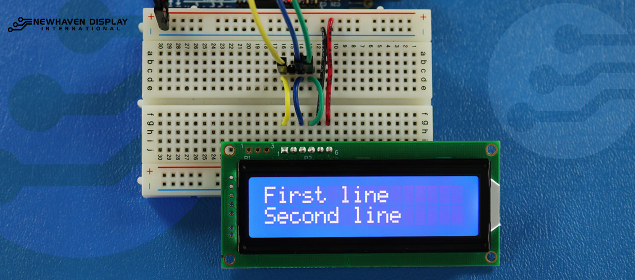
Anzeige von Text in der ersten und zweiten Zeile
Mit diesem Code wird der Text "Erste Zeile" in der ersten Zeile und "Zweite Zeile" in der zweiten Zeile angezeigt.
/*****************************************************
  This code was written for the Arduino UNO using SPI Interface.
  This code displays text in row one and row two of LCD.
  /*  SPI Wiring Reference for: NHD-0216K3Z-NSW-BBW-V3
  ---------------------------
  LCD         |   Arduino
  ---------------------------
  1(SPISS)  --> 12
  2(SDO)    --> No Connect
  3(SCK)    --> 10
  4(SDA)    --> 11
  5(VSS)    --> Ground
  6(VDD)    --> 5V
*/
/*****************************************************
   Arduino pin definition
  /*****************************************************/
#define SPISS_PIN   12
#define SDA_PIN     11
#define SCK_PIN     10
/*****************************************************
   SPI function to send command and data.
   For more information on SPI please visit our Support Center
  /*****************************************************/
void SPI_Out(unsigned char a) {
  digitalWrite(SPISS_PIN, LOW);
  for (int n = 0; n < 8; n++) {
    if ((a & 0x80) == 0x80) {
      digitalWrite(SDA_PIN, HIGH);
      delayMicroseconds(200);
    }
    else {
      digitalWrite(SDA_PIN, LOW);
    }
    delayMicroseconds(200);
    a = a << 1;
    digitalWrite(SCK_PIN, LOW);
    digitalWrite(SCK_PIN, HIGH);
    delayMicroseconds(200);
  }
  digitalWrite(SCK_PIN, HIGH);
  delayMicroseconds(200);
  digitalWrite(SPISS_PIN, HIGH);
}
/*****************************************************
   Set Arduino UNO IO ports as Output mode
  /*****************************************************/
void Set_Pins() {
  pinMode(SPISS_PIN, OUTPUT);
  pinMode(SCK_PIN, OUTPUT);
  pinMode(SDA_PIN, OUTPUT);
}
/*****************************************************
   Set LCD Contrast
  /*****************************************************/
void Set_Contrast() {
  SPI_Out(0xFE);              //prefix command
  SPI_Out(0x52);              //contrast command
  SPI_Out(0x28);              //set contrast value
  delayMicroseconds(500);
}
/*****************************************************
   Set LCD Backlight
  /*****************************************************/
void Set_Backlight() {
  SPI_Out(0xFE);             //prefix command
  SPI_Out(0x53);             //backlight command
  SPI_Out(0x08);             //set backlight value
  delayMicroseconds(100);
}
/*****************************************************
   Clear LCD
  /*****************************************************/
void Clear_Display() {
  SPI_Out(0xFE);             //prefix command
  SPI_Out(0x51);             //clear display command
  delayMicroseconds(1500);
}
/*****************************************************
   Write "First Line" to row one on LCD
  /*****************************************************/
void Send_First_Line_Text() {
  SPI_Out(0x46); // F
  SPI_Out(0x69); // i
  SPI_Out(0x72); // r
  SPI_Out(0x73); // s
  SPI_Out(0x74); // t
  SPI_Out(0x20); // blank space
  SPI_Out(0x6c); // l
  SPI_Out(0x69); // i
  SPI_Out(0x6e); // n
  SPI_Out(0x65); // e
}
/*****************************************************
   Write "Second Line" to row two on LCD
  /*****************************************************/
void Send_Second_Line_Text() {
  SPI_Out(0x53); // S
  SPI_Out(0x65); // e
  SPI_Out(0x63); // c
  SPI_Out(0x6f); // o
  SPI_Out(0x6e); // n
  SPI_Out(0x64); // d
  SPI_Out(0x20); // blank space
  SPI_Out(0x6c); // l
  SPI_Out(0x69); // i
  SPI_Out(0x6e); // n
  SPI_Out(0x65); // e
}
/*****************************************************
   Set Row address
   Line = 1 sets for first row
   Line = 2 sets for second row
  /*****************************************************/
void Set_Row(int line) {
  SPI_Out(0xfe);      //prefix command
  SPI_Out(0x45);      //set cursor command
  if (line == 1) {
    SPI_Out(0x00);    //cursor position: row one, column one
  }
  else if (line == 2) {
    SPI_Out(0x40);    //cursor position: row two, column one
  }
  delayMicroseconds(100);
}
/*****************************************************
     Main function
  /*****************************************************/
void setup() {
  Set_Pins();         //set IO ports
  Set_Contrast();     //set display contrast
  Set_Backlight();    //set display backlight
  Clear_Display();    //clear display
  Set_Row(1);
  Send_First_Line_Text();       //writes to first line of display
  Set_Row(2);
  Send_Second_Line_Text();      //writes to second line of display
  delay(1000);
}
void loop() {
}
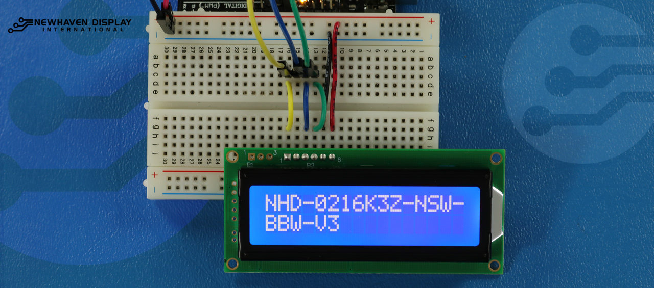
Langtext anzeigen
Dieser Code zeigt Text an, der bis zur zweiten Zeile reicht. In diesem Beispiel wird der TextNHD-0216K3Z-NSW-BBW-V3" angezeigt.
/*****************************************************
  This code displays the part number: NHD-0216K3Z-NSW-BBW-V3.
  /*  SPI Wiring Reference for: NHD-0216K3Z-NSW-BBW-V3
  ---------------------------
  LCD         |   Arduino
  ---------------------------
  1(SPISS)  --> 12
  2(SDO)    --> No Connect
  3(SCK)    --> 10
  4(SDA)    --> 11
  5(VSS)    --> Ground
  6(VDD)    --> 5V
*/
/*****************************************************
   Arduino pin definition
  /*****************************************************/
#define SPISS_PIN   12
#define SDA_PIN     11
#define SCK_PIN     10
/*****************************************************
   SPI function to send command and data.
   For more information on SPI please visit our Support Center
  /*****************************************************/
void SPI_Out(unsigned char a) {
  digitalWrite(SPISS_PIN, LOW);
  for (int n = 0; n < 8; n++) {
    if ((a & 0x80) == 0x80) {
      digitalWrite(SDA_PIN, HIGH);
      delayMicroseconds(200);
    }
    else {
      digitalWrite(SDA_PIN, LOW);
    }
    delayMicroseconds(200);
    a = a << 1;
    digitalWrite(SCK_PIN, LOW);
    digitalWrite(SCK_PIN, HIGH);
    delayMicroseconds(200);
  }
  digitalWrite(SCK_PIN, HIGH);
  delayMicroseconds(200);
  digitalWrite(SPISS_PIN, HIGH);
}
/*****************************************************
   Set Arduino UNO IO ports as Output mode
  /*****************************************************/
void Set_Pins() {
  pinMode(SPISS_PIN, OUTPUT);
  pinMode(SCK_PIN, OUTPUT);
  pinMode(SDA_PIN, OUTPUT);
}
/*****************************************************
   Set LCD Contrast
  /*****************************************************/
void Set_Contrast() {
  SPI_Out(0xFE);              //prefix command
  SPI_Out(0x52);              //contrast command
  SPI_Out(0x28);              //set contrast value
  delayMicroseconds(500);
}
/*****************************************************
   Set LCD Backlight
  /*****************************************************/
void Set_Backlight() {
  SPI_Out(0xFE);             //prefix command
  SPI_Out(0x53);             //backlight command
  SPI_Out(0x08);             //set backlight value
  delayMicroseconds(100);
}
/*****************************************************
   Clear LCD
  /*****************************************************/
void Clear_Display() {
  SPI_Out(0xFE);             //prefix command
  SPI_Out(0x51);             //clear display command
  delayMicroseconds(1500);
}
/*****************************************************
   Set cursor
   Mode = 0 sets Blinking cursor off
   Mode = 1 sets Blinking cursor on
  /*****************************************************/
void Set_Cursor(int mode) {
  SPI_Out(0xfe);          //prefix command
  if (mode == 0) {
    SPI_Out(0x4c);        //Blinking cursor off
  }
  else if (mode == 1) {
    SPI_Out(0x4b);        //Blinking cursor on
  }
  delayMicroseconds(100);
}
/*****************************************************
   Set Row address
   Line = 1 sets for first row
   Line = 2 sets for second row
  /*****************************************************/
void Set_Row(int line) {
  SPI_Out(0xfe);      //prefix command
  SPI_Out(0x45);      //set cursor command
  if (line == 1) {
    SPI_Out(0x00);    //cursor position: row one, column one
  }
  else if (line == 2) {
    SPI_Out(0x40);    //cursor position: row two, column one
  }
  delayMicroseconds(100);
}
/*****************************************************
   Write "NHD-0216K3Z-NSW-BBW-V3" to LCD
  /*****************************************************/
void Part_Number() {
  Set_Row(1);
  SPI_Out(0x4e); // N
  SPI_Out(0x48); // H
  SPI_Out(0x44); // D
  SPI_Out(0xb0); // -
  SPI_Out(0x30); // 0
  SPI_Out(0x32); // 2
  SPI_Out(0x31); // 1
  SPI_Out(0x36); // 6
  SPI_Out(0x4b); // K
  SPI_Out(0x33); // 3
  SPI_Out(0x5a); // Z
  SPI_Out(0xb0); // -
  SPI_Out(0x4e); // N
  SPI_Out(0x53); // S
  SPI_Out(0x57); // W
  SPI_Out(0xb0); // -
  Set_Row(2);
  SPI_Out(0x42); // B
  SPI_Out(0x42); // B
  SPI_Out(0x57); // W
  SPI_Out(0xb0); // -
  SPI_Out(0x56); // V
  SPI_Out(0x33); // 3
}
/*****************************************************
     Main function
  /*****************************************************/
void setup() {
  Set_Pins();         //set IO ports
  Set_Cursor(0);      //turns off blinking cursor
  Set_Contrast();     //set display contrast
  Set_Backlight();    //set display backlight
  Clear_Display();    //clear display
  Part_Number();      //display "NHD-0216K3Z-NSW-BBW-V3"
}
void loop() {
}
Blinken - Text mit blinkendem Cursor anzeigen
Dieser Code zeigt Text mit einem blinkenden Cursor an. In diesem Beispiel wird der TextNHD-0216K3Z-NSW-BBW-V3" angezeigt.
/*****************************************************
  This code displays the part number: NHD-0216K3Z-NSW-BBW-V3 with cursor on.
  /*  SPI Wiring Reference for: NHD-0216K3Z-NSW-BBW-V3
  ---------------------------
  LCD         |   Arduino
  ---------------------------
  1(SPISS)  --> 12
  2(SDO)    --> No Connect
  3(SCK)    --> 10
  4(SDA)    --> 11
  5(VSS)    --> Ground
  6(VDD)    --> 5V
*/
/*****************************************************
   Arduino pin definition
  /*****************************************************/
#define SPISS_PIN   12
#define SDA_PIN     11
#define SCK_PIN     10
/*****************************************************
   SPI function to send command and data.
   For more information on SPI please visit our Support Center
  /*****************************************************/
void SPI_Out(unsigned char a) {
  digitalWrite(SPISS_PIN, LOW);
  for (int n = 0; n < 8; n++) {
    if ((a & 0x80) == 0x80) {
      digitalWrite(SDA_PIN, HIGH);
      delayMicroseconds(200);
    }
    else {
      digitalWrite(SDA_PIN, LOW);
    }
    delayMicroseconds(200);
    a = a << 1;
    digitalWrite(SCK_PIN, LOW);
    digitalWrite(SCK_PIN, HIGH);
    delayMicroseconds(200);
  }
  digitalWrite(SCK_PIN, HIGH);
  delayMicroseconds(200);
  digitalWrite(SPISS_PIN, HIGH);
}
/*****************************************************
   Set Arduino UNO IO ports as Output mode
  /*****************************************************/
void Set_Pins() {
  pinMode(SPISS_PIN, OUTPUT);
  pinMode(SCK_PIN, OUTPUT);
  pinMode(SDA_PIN, OUTPUT);
}
/*****************************************************
   Set LCD Contrast
  /*****************************************************/
void Set_Contrast() {
  SPI_Out(0xFE);              //prefix command
  SPI_Out(0x52);              //contrast command
  SPI_Out(0x28);              //set contrast value
  delayMicroseconds(500);
}
/*****************************************************
   Set LCD Backlight
  /*****************************************************/
void Set_Backlight() {
  SPI_Out(0xFE);             //prefix command
  SPI_Out(0x53);             //backlight command
  SPI_Out(0x08);             //set backlight value
  delayMicroseconds(100);
}
/*****************************************************
   Clear LCD
  /*****************************************************/
void Clear_Display() {
  SPI_Out(0xFE);             //prefix command
  SPI_Out(0x51);             //clear display command
  delayMicroseconds(1500);
}
/*****************************************************
   Set cursor
   Mode = 0 sets Blinking cursor off
   Mode = 1 sets Blinking cursor on
  /*****************************************************/
void Set_Cursor(int mode) {
  SPI_Out(0xfe);          //prefix command
  if (mode == 0) {
    SPI_Out(0x4c);        //Blinking cursor off
  }
  else if (mode == 1) {
    SPI_Out(0x4b);        //Blinking cursor on
  }
  delayMicroseconds(100);
}
/*****************************************************
   Set Row address
   Line = 1 sets for first row
   Line = 2 sets for second row
  /*****************************************************/
void Set_Row(int line) {
  SPI_Out(0xfe);      //prefix command
  SPI_Out(0x45);      //set cursor command
  if (line == 1) {
    SPI_Out(0x00);    //cursor position: row one, column one
  }
  else if (line == 2) {
    SPI_Out(0x40);    //cursor position: row two, column one
  }
  delayMicroseconds(100);
}
/*****************************************************
   Write "NHD-0216K3Z-NSW-BBW-V3" to LCD
   delay(500) = 500 Milliseconds
  /*****************************************************/
void Part_Number() {
  Set_Row(1);
  SPI_Out(0x4e); // N
  delay(500);
  SPI_Out(0x48); // H
  delay(500);
  SPI_Out(0x44); // D
  delay(500);
  SPI_Out(0xb0); // -
  delay(500);
  SPI_Out(0x30); // 0
  delay(500);
  SPI_Out(0x32); // 2
  delay(500);
  SPI_Out(0x31); // 1
  delay(500);
  SPI_Out(0x36); // 6
  delay(500);
  SPI_Out(0x4b); // K
  delay(500);
  SPI_Out(0x33); // 3
  delay(500);
  SPI_Out(0x5a); // Z
  delay(500);
  SPI_Out(0xb0); // -
  delay(500);
  SPI_Out(0x4e); // N
  delay(500);
  SPI_Out(0x53); // S
  delay(500);
  SPI_Out(0x57); // W
  delay(500);
  SPI_Out(0xb0); // -
  Set_Row(2);
  delay(500);
  SPI_Out(0x42); // B
  delay(500);
  SPI_Out(0x42); // B
  delay(500);
  SPI_Out(0x57); // W
  delay(500);
  SPI_Out(0xb0); // -
  delay(500);
  SPI_Out(0x56); // V
  delay(500);
  SPI_Out(0x33); // 3
}
/*****************************************************
     Main function
  /*****************************************************/
void setup() {
  Set_Pins();         //set IO ports
  Set_Contrast();     //set display contrast
  Set_Backlight();    //set display backlight
  Clear_Display();    //clear display
  Set_Cursor(1);      //turns on blinking cursor
  Part_Number();      //display "NHD-0216K3Z-NSW-BBW-V3"
}
void loop() {
}
Cursor + Autoscroll-Text
Dieser Code zeigt zunächst den Text mit dem Cursor an und initialisiert dann den automatischen Bildlauf nach rechts.
/*****************************************************
  This code was written for the Arduino UNO using SPI Interface.
  This code displays the part number: NHD-0216K3Z-NSW-BBW-V3 while shifting to the right with a blinking cursor.
  /*  SPI Wiring Reference for: NHD-0216K3Z-NSW-BBW-V3
  ---------------------------
  LCD         |   Arduino
  ---------------------------
  1(SPISS)  --> 12
  2(SDO)    --> No Connect
  3(SCK)    --> 10
  4(SDA)    --> 11
  5(VSS)    --> Ground
  6(VDD)    --> 5V
*/
/*****************************************************
   Arduino pin definition
  /*****************************************************/
#define SPISS_PIN   12
#define SDA_PIN     11
#define SCK_PIN     10
/*****************************************************
   SPI function to send command and data.
   For more information on SPI please visit our Support Center
  /*****************************************************/
void SPI_Out(unsigned char a) {
  digitalWrite(SPISS_PIN, LOW);
  for (int n = 0; n < 8; n++) {
    if ((a & 0x80) == 0x80) {
      digitalWrite(SDA_PIN, HIGH);
      delayMicroseconds(200);
    }
    else {
      digitalWrite(SDA_PIN, LOW);
    }
    delayMicroseconds(200);
    a = a << 1;
    digitalWrite(SCK_PIN, LOW);
    digitalWrite(SCK_PIN, HIGH);
    delayMicroseconds(200);
  }
  digitalWrite(SCK_PIN, HIGH);
  delayMicroseconds(200);
  digitalWrite(SPISS_PIN, HIGH);
}
/*****************************************************
   Set Arduino UNO IO ports as Output mode
  /*****************************************************/
void Set_Pins() {
  pinMode(SPISS_PIN, OUTPUT);
  pinMode(SCK_PIN, OUTPUT);
  pinMode(SDA_PIN, OUTPUT);
}
/*****************************************************
   Set LCD Contrast
  /*****************************************************/
void Set_Contrast() {
  SPI_Out(0xFE);              //prefix command
  SPI_Out(0x52);              //contrast command
  SPI_Out(0x28);              //set contrast value
  delayMicroseconds(500);
}
/*****************************************************
   Set LCD Backlight
  /*****************************************************/
void Set_Backlight() {
  SPI_Out(0xFE);             //prefix command
  SPI_Out(0x53);             //backlight command
  SPI_Out(0x08);             //set backlight value
  delayMicroseconds(100);
}
/*****************************************************
   Clear LCD
  /*****************************************************/
void Clear_Display() {
  SPI_Out(0xFE);             //prefix command
  SPI_Out(0x51);             //clear display command
  delayMicroseconds(1500);
}
/*****************************************************
   Set cursor
   Mode = 0 sets Blinking cursor off
   Mode = 1 sets Blinking cursor on
  /*****************************************************/
void Set_Cursor(int mode) {
  SPI_Out(0xfe);          //prefix command
  if (mode == 0) {
    SPI_Out(0x4c);        //Blinking cursor off
  }
  else if (mode == 1) {
    SPI_Out(0x4b);        //Blinking cursor on
  }
  delayMicroseconds(100);
}
/*****************************************************
   Set Row address
   Line = 1 sets for first row
   Line = 2 sets for second row
  /*****************************************************/
void Set_Row(int line) {
  SPI_Out(0xfe);      //prefix command
  SPI_Out(0x45);      //set cursor command
  if (line == 1) {
    SPI_Out(0x00);    //cursor position: row one, column one
  }
  else if (line == 2) {
    SPI_Out(0x40);    //cursor position: row two, column one
  }
  delayMicroseconds(100);
}
/*****************************************************
   Write "NHD-0216K3Z-NSW-BBW-V3" to LCD
  /*****************************************************/
void Part_Number() {
    Set_Row(1);
  SPI_Out(0x4e); // N
  SPI_Out(0x48); // H
  SPI_Out(0x44); // D
  SPI_Out(0xb0); // -
  SPI_Out(0x30); // 0
  SPI_Out(0x32); // 2
  SPI_Out(0x31); // 1
  SPI_Out(0x36); // 6
  SPI_Out(0x4b); // K
  SPI_Out(0x33); // 3
  SPI_Out(0x5a); // Z
  SPI_Out(0xb0); // -
  SPI_Out(0x4e); // N
  SPI_Out(0x53); // S
  SPI_Out(0x57); // W
  SPI_Out(0xb0); // -
  Set_Row(2);
  SPI_Out(0x42); // B
  SPI_Out(0x42); // B
  SPI_Out(0x57); // W
  SPI_Out(0xb0); // -
  SPI_Out(0x56); // V
  SPI_Out(0x33); // 3
}
/*****************************************************
   Set Shifting mode
   Mode = 0 Move display one place to the left
   Mode = 1 Move display one place to the right
   delay(500) = 500 Milliseconds
  /*****************************************************/
void Set_Shift(int mode) {
  SPI_Out(0xfe);      //prefix command
  if (mode == 0) {
    SPI_Out(0x55);    //Move display one place to the left
  }
  else if (mode == 1) {
    SPI_Out(0x56);    //Move display one place to the right
  }
  delay(500);
}
/*****************************************************
     Main function
  /*****************************************************/
void setup() {
  Set_Pins();         //set IO ports
  Set_Contrast();     //set display contrast
  Set_Backlight();    //set display backlight
  Clear_Display();    //clear display
  Set_Cursor(1);      //turns on blinking cursor
  Part_Number();      //display "NHD-0216K3Z-NSW-BBW-V3"
}
/*****************************************************
     Loop function
  /*****************************************************/
void loop() {
  Set_Shift(1);     //shift display to the right
}
Automatisch rollender Text
Dieser Code lässt den TextNHD-0216K3Z-NSW-BBW-V3" automatisch durchlaufen.
/*****************************************************
  This code was written for the Arduino UNO using SPI Interface.
  This code displays the part number: NHD-0216K3Z-NSW-BBW-V3 while shifting to the right.
  /*  SPI Wiring Reference for: NHD-0216K3Z-NSW-BBW-V3
  ---------------------------
  LCD         |   Arduino
  ---------------------------
  1(SPISS)  --> 12
  2(SDO)    --> No Connect
  3(SCK)    --> 10
  4(SDA)    --> 11
  5(VSS)    --> Ground
  6(VDD)    --> 5V
*/
/*****************************************************
   Arduino pin definition
  /*****************************************************/
#define SPISS_PIN   12
#define SDA_PIN     11
#define SCK_PIN     10
/*****************************************************
   SPI function to send command and data.
   For more information on SPI please visit our Support Center
  /*****************************************************/
void SPI_Out(unsigned char a) {
  digitalWrite(SPISS_PIN, LOW);
  for (int n = 0; n < 8; n++) {
    if ((a & 0x80) == 0x80) {
      digitalWrite(SDA_PIN, HIGH);
      delayMicroseconds(200);
    }
    else {
      digitalWrite(SDA_PIN, LOW);
    }
    delayMicroseconds(200);
    a = a << 1;
    digitalWrite(SCK_PIN, LOW);
    digitalWrite(SCK_PIN, HIGH);
    delayMicroseconds(200);
  }
  digitalWrite(SCK_PIN, HIGH);
  delayMicroseconds(200);
  digitalWrite(SPISS_PIN, HIGH);
}
/*****************************************************
   Set Arduino UNO IO ports as Output mode
  /*****************************************************/
void Set_Pins() {
  pinMode(SPISS_PIN, OUTPUT);
  pinMode(SCK_PIN, OUTPUT);
  pinMode(SDA_PIN, OUTPUT);
}
/*****************************************************
   Set LCD Contrast
  /*****************************************************/
void Set_Contrast() {
  SPI_Out(0xFE);              //prefix command
  SPI_Out(0x52);              //contrast command
  SPI_Out(0x28);              //set contrast value
  delayMicroseconds(500);
}
/*****************************************************
   Set LCD Backlight
  /*****************************************************/
void Set_Backlight() {
  SPI_Out(0xFE);             //prefix command
  SPI_Out(0x53);             //backlight command
  SPI_Out(0x08);             //set backlight value
  delayMicroseconds(100);
}
/*****************************************************
   Clear LCD
  /*****************************************************/
void Clear_Display() {
  SPI_Out(0xFE);             //prefix command
  SPI_Out(0x51);             //clear display command
  delayMicroseconds(1500);
}
/*****************************************************
   Set cursor
   Mode = 0 sets Blinking cursor off
   Mode = 1 sets Blinking cursor on
  /*****************************************************/
void Set_Cursor(int mode) {
  SPI_Out(0xfe);          //prefix command
  if (mode == 0) {
    SPI_Out(0x4c);        //Blinking cursor off
  }
  else if (mode == 1) {
    SPI_Out(0x4b);        //Blinking cursor on
  }
  delayMicroseconds(100);
}
/*****************************************************
   Set Row address
   Line = 1 sets for first row
   Line = 2 sets for second row
  /*****************************************************/
void Set_Row(int line) {
  SPI_Out(0xfe);      //prefix command
  SPI_Out(0x45);      //set cursor command
  if (line == 1) {
    SPI_Out(0x00);    //cursor position: row one, column one
  }
  else if (line == 2) {
    SPI_Out(0x40);    //cursor position: row two, column one
  }
  delayMicroseconds(100);
}
/*****************************************************
   Write "NHD-0216K3Z-NSW-BBW-V3" to LCD
  /*****************************************************/
void Part_Number() {
    Set_Row(1);
  SPI_Out(0x4e); // N
  SPI_Out(0x48); // H
  SPI_Out(0x44); // D
  SPI_Out(0xb0); // -
  SPI_Out(0x30); // 0
  SPI_Out(0x32); // 2
  SPI_Out(0x31); // 1
  SPI_Out(0x36); // 6
  SPI_Out(0x4b); // K
  SPI_Out(0x33); // 3
  SPI_Out(0x5a); // Z
  SPI_Out(0xb0); // -
  SPI_Out(0x4e); // N
  SPI_Out(0x53); // S
  SPI_Out(0x57); // W
  SPI_Out(0xb0); // -
  Set_Row(2);
  SPI_Out(0x42); // B
  SPI_Out(0x42); // B
  SPI_Out(0x57); // W
  SPI_Out(0xb0); // -
  SPI_Out(0x56); // V
  SPI_Out(0x33); // 3
}
/*****************************************************
   Set Shifting mode
   Mode = 0 Move display one place to the left
   Mode = 1 Move display one place to the right
   delay(500) = 500 Milliseconds
  /*****************************************************/
void Set_Shift(int mode) {
  SPI_Out(0xfe);      //prefix command
  if (mode == 0) {
    SPI_Out(0x55);    //Move display one place to the left
  }
  else if (mode == 1) {
    SPI_Out(0x56);    //Move display one place to the right
  }
  delay(500);
}
/*****************************************************
     Main function
  /*****************************************************/
void setup() {
  Set_Pins();         //set IO ports
  Set_Contrast();     //set display contrast
  Set_Backlight();    //set display backlight
  Clear_Display();    //clear display
  Set_Cursor(0);      //turns off blinking cursor
  Part_Number();      //display "NHD-0216K3Z-NSW-BBW-V3"
}
/*****************************************************
     Loop function
  /*****************************************************/
void loop() {
  Set_Shift(1);     //shift display to the right
}
Einstellen des LCD-Kontrasts
Dieser Code zeigt beim Ändern des Kontrasts den TextNHD-0216K3Z-NSW-BBW-V3" an.
    /*****************************************************
  This code was written for the Arduino UNO using SPI Interface.
  This code displays the part number: NHD-0216K3Z-NSW-BBW-V3 while changing the contrast.
  /*  SPI Wiring Reference for: NHD-0216K3Z-NSW-BBW-V3
  ---------------------------
  LCD         |   Arduino
  ---------------------------
  1(SPISS)  --> 12
  2(SDO)    --> No Connect
  3(SCK)    --> 10
  4(SDA)    --> 11
  5(VSS)    --> Ground
  6(VDD)    --> 5V
*/
/*****************************************************
   Arduino pin definition
  /*****************************************************/
#define SPISS_PIN   12
#define SDA_PIN     11
#define SCK_PIN     10
/*****************************************************
   SPI function to send command and data.
   For more information on SPI please visit our Support Center
  /*****************************************************/
void SPI_Out(unsigned char a) {
  digitalWrite(SPISS_PIN, LOW);
  for (int n = 0; n < 8; n++) {
    if ((a & 0x80) == 0x80) {
      digitalWrite(SDA_PIN, HIGH);
      delayMicroseconds(200);
    }
    else {
      digitalWrite(SDA_PIN, LOW);
    }
    delayMicroseconds(200);
    a = a << 1;
    digitalWrite(SCK_PIN, LOW);
    digitalWrite(SCK_PIN, HIGH);
    delayMicroseconds(200);
  }
  digitalWrite(SCK_PIN, HIGH);
  delayMicroseconds(200);
  digitalWrite(SPISS_PIN, HIGH);
}
/*****************************************************
   Set Arduino UNO IO ports as Output mode
  /*****************************************************/
void Set_Pins() {
  pinMode(SPISS_PIN, OUTPUT);
  pinMode(SCK_PIN, OUTPUT);
  pinMode(SDA_PIN, OUTPUT);
}
/*****************************************************
   Set LCD Contrast
  /*****************************************************/
void Set_Contrast() {
  SPI_Out(0xFE);              //prefix command
  SPI_Out(0x52);              //contrast command
  SPI_Out(0x32);              //set contrast value
  delayMicroseconds(500);
}
/*****************************************************
   Set LCD Backlight
  /*****************************************************/
void Set_Backlight() {
  SPI_Out(0xFE);             //prefix command
  SPI_Out(0x53);             //backlight command
  SPI_Out(0x08);             //set backlight value
  delayMicroseconds(100);
}
/*****************************************************
   Clear LCD
  /*****************************************************/
void Clear_Display() {
  SPI_Out(0xFE);             //prefix command
  SPI_Out(0x51);             //clear display command
  delayMicroseconds(1500);
}
/*****************************************************
   Set cursor
   Mode = 0 sets Blinking cursor off
   Mode = 1 sets Blinking cursor on
  /*****************************************************/
void Set_Cursor(int mode) {
  SPI_Out(0xfe);          //prefix command
  if (mode == 0) {
    SPI_Out(0x4c);        //Blinking cursor off
  }
  else if (mode == 1) {
    SPI_Out(0x4b);        //Blinking cursor on
  }
  delayMicroseconds(100);
}
/*****************************************************
   Set Row address
   Line = 1 sets for first row
   Line = 2 sets for second row
  /*****************************************************/
void Set_Row(int line) {
  SPI_Out(0xfe);      //prefix command
  SPI_Out(0x45);      //set cursor command
  if (line == 1) {
    SPI_Out(0x00);    //cursor position: row one, column one
  }
  else if (line == 2) {
    SPI_Out(0x40);    //cursor position: row two, column one
  }
  delayMicroseconds(100);
}
/*****************************************************
   Write "NHD-0216K3Z-NSW-BBW-V3" to LCD
  /*****************************************************/
void Part_Number() {
  Set_Row(1);
  SPI_Out(0x4e); // N
  SPI_Out(0x48); // H
  SPI_Out(0x44); // D
  SPI_Out(0xb0); // -
  SPI_Out(0x30); // 0
  SPI_Out(0x32); // 2
  SPI_Out(0x31); // 1
  SPI_Out(0x36); // 6
  SPI_Out(0x4b); // K
  SPI_Out(0x33); // 3
  SPI_Out(0x5a); // Z
  SPI_Out(0xb0); // -
  SPI_Out(0x4e); // N
  SPI_Out(0x53); // S
  SPI_Out(0x57); // W
  SPI_Out(0xb0); // -
  Set_Row(2);
  SPI_Out(0x42); // B
  SPI_Out(0x42); // B
  SPI_Out(0x57); // W
  SPI_Out(0xb0); // -
  SPI_Out(0x56); // V
  SPI_Out(0x33); // 3
}
/*****************************************************
  Function to:
    - change contrast from highest --> lowest
    - change contrast from lowest  --> highest
  delay(100) = 100 Milliseconds
  /*****************************************************/
void Contrast_Cycle() {
  for (int x = 50; x >= 0; x--) {
    SPI_Out(0xFE);             //High to Low contrast loop
    SPI_Out(0x52);
    SPI_Out(x);
    delay(100);
  }
  for (int x = 0; x <= 50; x++) {
    SPI_Out(0xFE);             //Low to High contrats loop
    SPI_Out(0x52);
    SPI_Out(x);
    delay(100);
  }
}
/*****************************************************
     Main function
  /*****************************************************/
void setup() {
  Set_Pins();         //set IO ports
  Set_Contrast();     //set display contrast
  Set_Backlight();    //set display backlight
  Clear_Display();    //clear display
  Set_Cursor(0);      //turns off blinking cursor
  Part_Number();      //display "NHD-0216K3Z-NSW-BBW-V3"
}
/*****************************************************
     Loop function
  /*****************************************************/
void loop() {
  Contrast_Cycle(); //cycle through contrast
}
So verwenden Sie die LCD-Hintergrundbeleuchtung
There are different methods for controlling or adjusting the backlight of the LCD. Two of the most common ways of controlling or adjusting the LCD backlight are via a command or a potentiometer.
Bei unseren seriellen Displays, wie dem NHD-0216K3Z-NSW-BBW-V3, kann die Hintergrundbeleuchtung über einen Befehl gesteuert werden. Die Backlight_loop() stellt den Helligkeitswert der Hintergrundbeleuchtung in einer konstanten Schleife vom höchsten zum niedrigsten und dann vom niedrigsten zum höchsten Wert ein.
Der folgende Code zeigt den TextNHD-0216K3Z-NSW-BBW-V3" an, während die Intensität der Hintergrundbeleuchtung geändert wird.
        /*****************************************************
  This code was written for the Arduino UNO using SPI Interface.
  This code displays the part number: NHD-0216K3Z-NSW-BBW-V3 while changing the backlight.
  /*  SPI Wiring Reference for: NHD-0216K3Z-NSW-BBW-V3
  ---------------------------
  LCD         |   Arduino
  ---------------------------
  1(SPISS)  --> 12
  2(SDO)    --> No Connect
  3(SCK)    --> 10
  4(SDA)    --> 11
  5(VSS)    --> Ground
  6(VDD)    --> 5V
*/
/*****************************************************
   Arduino pin definition
  /*****************************************************/
#define SPISS_PIN   12
#define SDA_PIN     11
#define SCK_PIN     10
/*****************************************************
   SPI function to send command and data.
   For more information on SPI please visit our Support Center
  /*****************************************************/
void SPI_OUT(unsigned char a) {
  digitalWrite(SPISS_PIN, LOW);
  for (int n = 0; n < 8; n++) {
    if ((a & 0x80) == 0x80) {
      digitalWrite(SDA_PIN, HIGH);
      delayMicroseconds(200);
    }
    else {
      digitalWrite(SDA_PIN, LOW);
    }
    delayMicroseconds(200);
    a = a << 1;
    digitalWrite(SCK_PIN, LOW);
    digitalWrite(SCK_PIN, HIGH);
    delayMicroseconds(200);
  }
  digitalWrite(SCK_PIN, HIGH);
  delayMicroseconds(200);
  digitalWrite(SPISS_PIN, HIGH);
}
/*****************************************************
   Set Arduino UNO IO ports as Output mode
  /*****************************************************/
void Set_Pins() {
  pinMode(SPISS_PIN, OUTPUT);
  pinMode(SCK_PIN, OUTPUT);
  pinMode(SDA_PIN, OUTPUT);
}
/*****************************************************
   Set LCD Contrast
  /*****************************************************/
void Set_Contrast() {
  SPI_OUT(0xFE);              //prefix command
  SPI_OUT(0x52);              //contrast command
  SPI_OUT(0x28);              //set contrast value
  delayMicroseconds(500);
}
/*****************************************************
   Set LCD Backlight
  /*****************************************************/
void Set_Backlight() {
  SPI_OUT(0xFE);             //prefix command
  SPI_OUT(0x53);             //backlight command
  SPI_OUT(0x08);             //set backlight value
  delayMicroseconds(100);
}
/*****************************************************
   Clear LCD
  /*****************************************************/
void Clear_Display() {
  SPI_OUT(0xFE);             //prefix command
  SPI_OUT(0x51);             //clear display command
  delayMicroseconds(1500);
}
/*****************************************************
   Set cursor
   Mode = 0 sets Blinking cursor off
   Mode = 1 sets Blinking cursor on
  /*****************************************************/
void Set_Cursor(int mode) {
  SPI_OUT(0xfe);          //prefix command
  if (mode == 0) {
    SPI_OUT(0x4c);        //Blinking cursor off
  }
  else if (mode == 1) {
    SPI_OUT(0x4b);        //Blinking cursor on
  }
  delayMicroseconds(100);
}
/*****************************************************
   Set Row address
   Line = 1 sets for first row
   Line = 2 sets for second row
  /*****************************************************/
void Set_Row(int line) {
  SPI_OUT(0xfe);      //prefix command
  SPI_OUT(0x45);      //set cursor command
  if (line == 1) {
    SPI_OUT(0x00);    //cursor position: row one, column one
  }
  else if (line == 2) {
    SPI_OUT(0x40);    //cursor position: row two, column one
  }
  delayMicroseconds(100);
}
/*****************************************************
   Write "NHD-0216K3Z-NSW-BBW-V3" to LCD
  /*****************************************************/
void Part_Number() {
    Set_Row(1);
  SPI_OUT(0x4e); // N
  SPI_OUT(0x48); // H
  SPI_OUT(0x44); // D
  SPI_OUT(0xb0); // -
  SPI_OUT(0x30); // 0
  SPI_OUT(0x32); // 2
  SPI_OUT(0x31); // 1
  SPI_OUT(0x36); // 6
  SPI_OUT(0x4b); // K
  SPI_OUT(0x33); // 3
  SPI_OUT(0x5a); // Z
  SPI_OUT(0xb0); // -
  SPI_OUT(0x4e); // N
  SPI_OUT(0x53); // S
  SPI_OUT(0x57); // W
  SPI_OUT(0xb0); // -
  Set_Row(2);
  SPI_OUT(0x42); // B
  SPI_OUT(0x42); // B
  SPI_OUT(0x57); // W
  SPI_OUT(0xb0); // -
  SPI_OUT(0x56); // V
  SPI_OUT(0x33); // 3
}
/*****************************************************
  Function to:
    - change backlight from highest --> lowest
    - change backlight from lowest  --> highest
  delay(500) = 500 Milliseconds
  /*****************************************************/
void Backlight_loop() {
  for (int x = 8; x >= 0; x--) {
    SPI_OUT(0xFE);              //High to Low Backlight loop
    SPI_OUT(0x53);
    SPI_OUT(x);
    delay(500);
  }
  for (int x = 0; x <= 8; x++) {
    SPI_OUT(0xFE);              //Low to High Backlight loop
    SPI_OUT(0x53);
    SPI_OUT(x);
    delay(500);
  }
}
/*****************************************************
     Main function
  /*****************************************************/
void setup() {
  Set_Pins();         //set IO ports
  Set_Contrast();     //set display contrast
  Set_Backlight();    //set display backlight
  Clear_Display();    //clear display
  Set_Cursor(0);      //turns off blinking cursor
  Part_Number();      //display "NHD-0216K3Z-NSW-BBW-V3"
}
/*****************************************************
     Loop function
  /*****************************************************/
void loop() {
  Backlight_loop();   //High to Low Backlight loop
}
Zeichen/Schrifttabellen
Dieser Code zeigt Zeichen aus der Schriftartentabelle an, die in der LCD-Anzeige enthalten ist.
        /*****************************************************
  This code was written for the Arduino UNO using SPI Interface.
  This code displays the font table characters.
  /*  SPI Wiring Reference for: NHD-0216K3Z-NSW-BBW-V3
  ---------------------------
  LCD         |   Arduino
  ---------------------------
  1(SPISS)  --> 12
  2(SDO)    --> No Connect
  3(SCK)    --> 10
  4(SDA)    --> 11
  5(VSS)    --> Ground
  6(VDD)    --> 5V
*/
/*****************************************************
   Arduino pin definition
  /*****************************************************/
#define SPISS_PIN   12
#define SDA_PIN     11
#define SCK_PIN     10
/*****************************************************
   SPI function to send command and data.
   For more information on SPI please visit our Support Center
  /*****************************************************/
void SPI_out(unsigned char a) {
  digitalWrite(SPISS_PIN, LOW);
  for (int n = 0; n < 8; n++) {
    if ((a & 0x80) == 0x80) {
      digitalWrite(SDA_PIN, HIGH);
      delayMicroseconds(200);
    }
    else {
      digitalWrite(SDA_PIN, LOW);
    }
    delayMicroseconds(200);
    a = a << 1;
    digitalWrite(SCK_PIN, LOW);
    digitalWrite(SCK_PIN, HIGH);
    delayMicroseconds(200);
  }
  digitalWrite(SCK_PIN, HIGH);
  delayMicroseconds(200);
  digitalWrite(SPISS_PIN, HIGH);
}
/*****************************************************
   Set Arduino UNO IO ports as Output mode
  /*****************************************************/
void Set_Pins() {
  pinMode(SPISS_PIN, OUTPUT);
  pinMode(SCK_PIN, OUTPUT);
  pinMode(SDA_PIN, OUTPUT);
}
/*****************************************************
   Set LCD Contrast
  /*****************************************************/
void Set_Contrast() {
  SPI_out(0xFE);              //prefix command
  SPI_out(0x52);              //contrast command
  SPI_out(0x28);              //set contrast value
  delayMicroseconds(500);
}
/*****************************************************
   Set LCD Backlight
  /*****************************************************/
void Set_Backlight() {
  SPI_out(0xFE);             //prefix command
  SPI_out(0x53);             //backlight command
  SPI_out(0x08);             //set backlight value
  delayMicroseconds(100);
}
/*****************************************************
   Clear LCD
  /*****************************************************/
void Clear_Display() {
  SPI_out(0xFE);             //prefix command
  SPI_out(0x51);             //clear display command
  delayMicroseconds(1500);
}
/*****************************************************
   Set cursor
   Mode = 0 sets Blinking cursor off
   Mode = 1 sets Blinking cursor on
  /*****************************************************/
void Set_Cursor(int mode) {
  SPI_out(0xfe);          //prefix command
  if (mode == 0) {
    SPI_out(0x4c);        //Blinking cursor off
  }
  else if (mode == 1) {
    SPI_out(0x4b);        //Blinking cursor on
  }
  delayMicroseconds(100);
}
/*****************************************************
   Set Row address
   Line = 1 sets for first row
   Line = 2 sets for second row
  /*****************************************************/
void Set_Row(int line) {
  SPI_out(0xfe);      //prefix command
  SPI_out(0x45);      //set cursor command
  if (line == 1) {
    SPI_out(0x00);    //cursor position: row one, column one
  }
  else if (line == 2) {
    SPI_out(0x40);    //cursor position: row two, column one
  }
  delayMicroseconds(100);
}
/*****************************************************
  Display font characters
    -change the row address every 16 characters displayed
    -used Clear_Display() function to clear the display
     and change the row to the first row
  delay(500) = 500 Milliseconds
  /*****************************************************/
void Font_Table_Characters() {
  Clear_Display();
  for (int i = 0; i < 64; i++) {
    if (i == 16 || i == 48) {
      Set_Row(2);
    }
    else if (i == 32 || i == 64) {
      Clear_Display();
      if (i == 64) {
        i = 0;
      }
    }
    SPI_out(i + 32);
    delay(500);
  }
}
/*****************************************************
     Main function
  /*****************************************************/
void setup() {
  Set_Pins();         //set IO ports
  Set_Contrast();     //set display contrast
  Set_Backlight();    //set display backlight
  Clear_Display();    //clear display
  Set_Cursor(0);      //turns off blinking cursor
}
/*****************************************************
     Loop function
  /*****************************************************/
void loop() {
  Font_Table_Characters();  //Display font characters
}
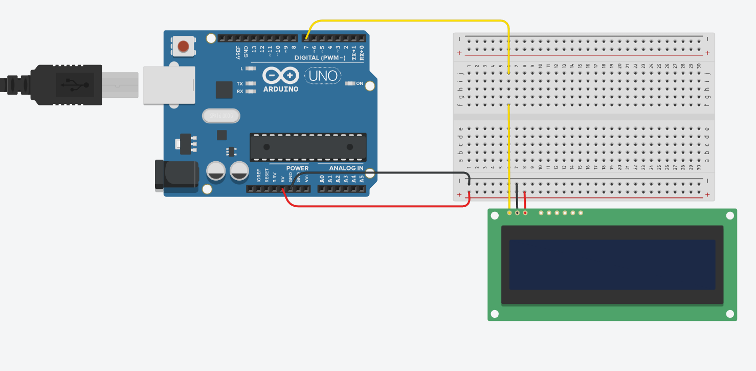
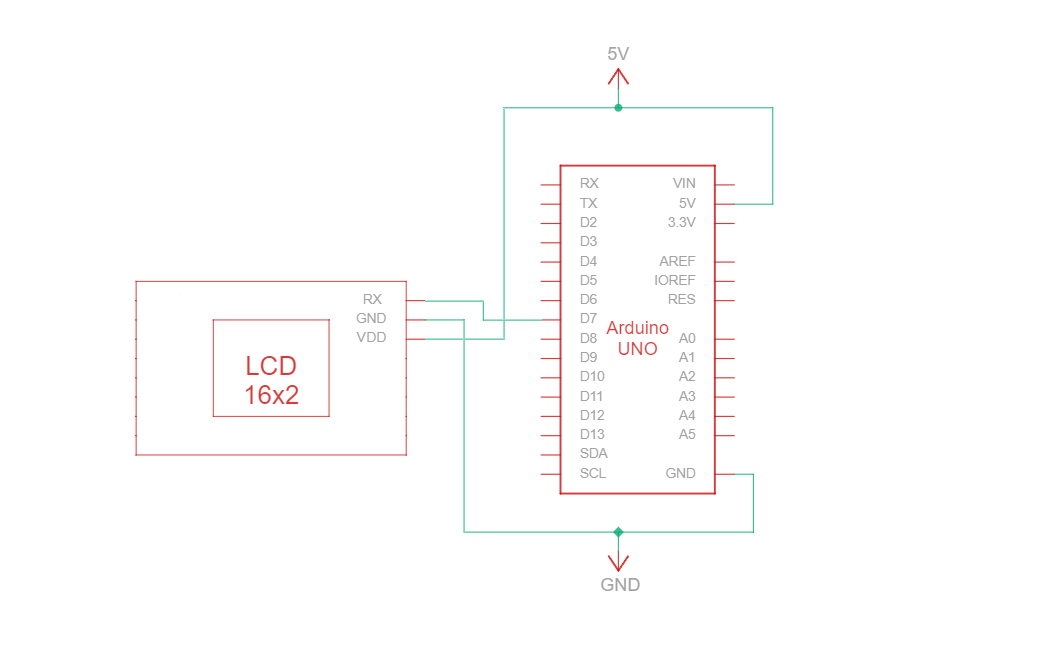
Schaltung - Anschlussplan und Schaltplan für RS232 TTL Kommunikation
RS232 TTL ist ein serielles Kommunikationsprotokoll, das RS232-Spezifikationen verwendet, aber mit TTL-Logikpegeln (0 V bis Vcc, typischerweise 3,3 V oder 5 V). Die RS232-TTL-Verbindungsschaltung zwischen Arduino und dem 16-Zeichen-Newhaven-Display verwendet nur drei Drähte:
| Arduino | LCD | Verbindungstyp |
|---|---|---|
| 5V Stift | Pin 3: V DD | Strom |
| Erdungsstift | Pin 2: Masse | Boden |
| Pin 7: Digitaler E/A-Pin | Stift 1: RX | RS-232 (TTL) Serieller Eingangsanschluss |
Note:
R1 and R2 on the display must be open to enable RS232 TTL as specified in the datasheet.
RS232 TTL Verdrahtungsschaltung
RS232 TTL-Schaltplan
We have created a detailed beginner-friendly tutorial on Instructables for RS232 TTL communication. The tutorial includes all the necessary steps to complete this project. Check it out here: www.instructables.com/Arduino-LCD-Tutorial/
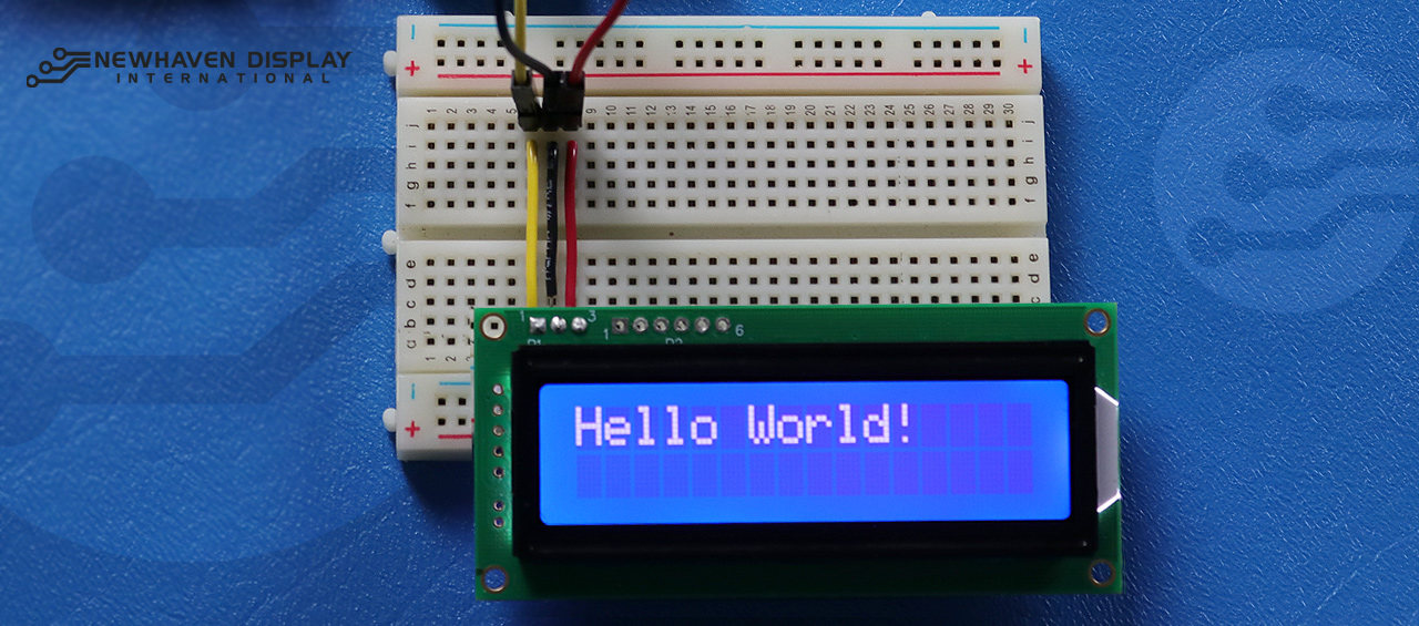
Arduino - LCD Hallo Welt! Code-Beispiel mit serieller RS232 TTL-Kommunikation
Das folgende Codebeispiel zeigt "Hello Word!" auf dem LCD unter Verwendung der RS232-TTL-Kommunikation an.
/***************************************************** This code was written for the Arduino UNO using RS-232 Interface. /* RS-232 Wiring Reference for: NHD-0216K3Z-NSW-BBW-V3 --------------------------- LCD | Arduino --------------------------- 1(RX) --> 7 2(VSS) --> Ground 3(VDD) --> 5V */ #define P1 7 //RX the pin on which to receive serial data. /***************************************************** RS-232 setup for command and data. For more information on RS-232 please visit our Support Center /*****************************************************/ #include#define RxPin P1 SoftwareSerial NHD_LCD = SoftwareSerial(P1, RxPin); /***************************************************** Set LCD Contrast /*****************************************************/ void Set_Contrast() { NHD_LCD.write(0xFE); //Prefix command NHD_LCD.write(0x52); //Contrast command NHD_LCD.write(0x28); //Set contrast value delayMicroseconds(500); } /***************************************************** Clear LCD /*****************************************************/ void Clear_display() { NHD_LCD.write(0xFE); //Prefix command NHD_LCD.write(0x51); //Clear Display delayMicroseconds(1500); } /***************************************************** Set Arduino UNO IO ports as Output mode /*****************************************************/ void Set_Pins() { pinMode(RxPin, OUTPUT); } /***************************************************** Set LCD Backlight /*****************************************************/ void Set_Backlight() { NHD_LCD.write(0xFE); //prefix command NHD_LCD.write(0x53); //Backlight command NHD_LCD.write(0x08); //Set backlight value delayMicroseconds(100); } /***************************************************** Set cursor Mode = 0 sets Blinking cursor off Mode = 1 sets Blinking cursor on /*****************************************************/ void Set_Cursor(int mode) { NHD_LCD.write(0xFE); //Prefix command if (mode == 0) { NHD_LCD.write(0x4c); //Turn blinking cursor off } else if (mode == 1) { NHD_LCD.write(0x4b); //Turn blinking cursor on } delayMicroseconds(100); } /***************************************************** Write "Hello World!" to LCD /*****************************************************/ void Hello_World() { NHD_LCD.write(0x48); // H NHD_LCD.write(0x65); // e NHD_LCD.write(0x6C); // l NHD_LCD.write(0x6C); // l NHD_LCD.write(0x6F); // o NHD_LCD.write(0x11); // Blank NHD_LCD.write(0x57); // W NHD_LCD.write(0x6f); // o NHD_LCD.write(0x72); // r NHD_LCD.write(0x6c); // l NHD_LCD.write(0x64); // d NHD_LCD.write(0x21); // ! } /***************************************************** Main function /*****************************************************/ void setup() { NHD_LCD.begin(9600); //Sets 9600 Baud Rate the display can receive and transmit data at a rate of 9600 bits per second by default. delay(15); Set_Pins(); //Set IO ports Set_Cursor(0); //Turns off blinking cursor Set_Contrast(); //Set display Contrast Set_Backlight(); //Set display Backlight Clear_display(); //Clear display Hello_World(); //Display "Hello Wolrd!" } void loop() { }
Fehlersuche für Ihr LCD - Arduino-Projekt
Im Folgenden werden wir einige allgemeine Schritte besprechen, die Sie unternehmen können, wenn Sie Probleme mit Ihrem Arduino-LCD-Projekt haben.
- Überprüfen Sie die Verdrahtung: Das häufigste Problem beim Anschluss eines LCD an einen Arduino ist eine falsche Verdrahtung. Überprüfen Sie Ihre Verdrahtungsanschlüsse anhand des mitgelieferten Anschlussplans und der Schaltung, um eine ordnungsgemäße Konnektivität sicherzustellen. Beachten Sie außerdem, dass das NHD-0216K3Z-NSW-BBW-V3 für den Betrieb mit SPI-, I2C- und RS232-TTL-Schnittstellen konfiguriert werden kann. Um mit der SPI-Schnittstelle zu arbeiten, muss ein 0-Ohm-Widerstand in den R2-Abschnitt der Platine eingelötet werden.
- Überprüfen Sie die Komponenten: Achten Sie auf sichtbare Anzeichen von Schäden am Arduino, am LCD oder an den Verbindungskabeln.
- Überprüfen Sie den Code: Stellen Sie sicher, dass der hochgeladene Code auf Ihrem Arduino korrekt und fehlerfrei ist.
- Überprüfen Sie die Stromversorgung: Vergewissern Sie sich, dass Ihre Stromquelle ausreicht, um sowohl den Arduino als auch das LCD zu versorgen.
- Testen Sie mit einem bekanntermaßen funktionierenden LCD: Wenn Sie immer noch Probleme haben, versuchen Sie, ein anderes, bekanntermaßen gutes LCD an Ihren Arduino anzuschließen. So können Sie feststellen, ob das Problem mit dem LCD oder dem Arduino-Board selbst zusammenhängt.
- Kontrast einstellen: Wenn Sie Probleme haben, den angezeigten Text auf dem LCD-Display zu sehen, versuchen Sie, den Kontrast mit der Softwarefunktion
Kontrast_einstellen()die oben beschrieben ist. Unterschiedliche Lichtverhältnisse können unterschiedliche Kontrasteinstellungen für eine optimale Sichtbarkeit erfordern. - Überprüfen Sie die Version der Arduino IDE: Stellen Sie sicher, dass Sie die neueste Version der Arduino IDE verwenden. Veraltete Versionen können Bugs enthalten oder mit Ihrem Projekt inkompatibel sein.
- Testen Sie einzelne Funktionen: Wenn Sie Probleme mit bestimmten Funktionen wie Bildlauf oder Kontraststeuerung haben, versuchen Sie, einfacheren Code wie das "Hello World!"-Beispiel auszuführen, um das Problem zu isolieren. So können Sie feststellen, ob das Problem mit dem Code oder der Hardware zusammenhängt.
- Suchen Sie Hilfe in der Community: Wenn Sie das Problem nach den oben genannten Schritten zur Fehlerbehebung nicht lösen können, sollten Sie die Online-Community um Hilfe bitten. Online-Foren, wie das Newhaven Display Support Forum, das Arduino Stack Exchange oder das Arduino.cc Forum, sind hervorragende Ressourcen, um Hilfe von erfahrenen Benutzern zu erhalten.
Wenn Sie diese Schritte zur Fehlersuche befolgen, sollten Sie in der Lage sein, die meisten Probleme im Zusammenhang mit dem Anschluss eines LCD an ein Arduino-Board zu diagnostizieren und zu lösen. Denken Sie daran, dass Geduld und Liebe zum Detail bei der Fehlersuche in Elektronikprojekten entscheidend sind.
Zusätzliche Ressourcen
- Arduino UNO offizielle Website.
- LCD 16x2 Produktbeschreibung.
- LCD 16x2 Produktdatenblatt und technische Daten.
- Einsteigerfreundliches Arduino-LCD Instructables Tutorial
- Character LCD Support Forum.
- Lesen Sie unseren Leitfaden für Einsteiger zum Prototyping von Displays.
- Zeichen LCD Beispielcode.
- Erfahren Sie, wie Sie Elektronik vor ESD schützen können.
- Erfahren Sie mehr über die verschiedenen Arten von LCDs.
- Erfahren Sie mehr über die LCD-Modi.