
RS232
An important aspect to consider when working with electronic devices is the type of data communication protocol they use. Serial communications are widely utilized in the electronics industry due to their relative simplicity and low hardware requirements compared to parallel interface communications.
This article will discuss an old but still used serial communication protocol - the RS-232.
In this article:
What is RS232?
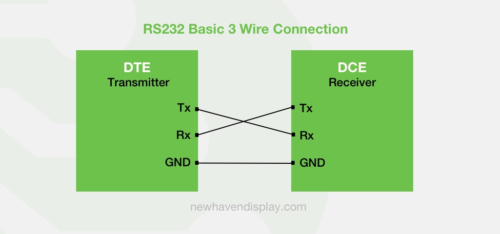
RS232 (Recommended Standard 232) is a serial binary data communication standard introduced in 1960. The standard defines pins and signals connecting between a data terminal equipment (DTE) and a Data Communications Equipment (DCE).
RS-232 Characteristics Overview
- Serial data communication
- Unbalanced transmission
- Point-to-point communication
- Asynchronous communication
- Full duplex communication
Related: Serial vs Parallel Communication
Before the RS232 standard, devices were linked via analog telephone voice lines that required modems for signal translation which were prone to data errors and required complex configurations.
The RS232 standard was developed to ensure reliable data communication and to promote compatibility between devices produced by different manufacturers, thereby promoting mass production and competition.
Who created the RS232 standard?
The RS232 standard was developed by the Telecommunication Industry Association (TIA) hence also referenced as EIA/TIA-232. The original and other versions of the RS232 standard can only be purchased via the official TIA website. You can find many free resources online to help you understand and implement RS232 into your next project.
A common RS232 wiring connection includes 3 wire signal connections, Tx (Transmitter), Rx (Receiver), and GND (Ground).
Over the 60+ years since the RS232 standard was developed, the Electronic Industries Association has published several modifications and name changes, more notably the EIA232, introduced in 1991, and TIA232, introduced in 1997.
RS232 Version History
- EIA RS-232 (May 1960)
- EIA RS-232-A (October 1963)
- EIA RS-232-B (October 1965)
- EIA RS-232-C (June 1981)
- EIA EIA-232-D (November 1986)
- TIA TIA/EIA-232-E (July 1991)
- TIA TIA/EIA-232-F (October 1997)
- ANSI/TIA-232-F-1997 (October 1997)
- TIA TIA-232-F (October 1997)
Once a standard in many computer devices, including printers, computer mice, keyboards, and joysticks, the RS-232 communication standard was replaced in many computer peripherals by the USB communication standard in the early 2000s. More recent standards, such as the RS485, SPI, I²C, and CAN, have gained popularity because of their more advanced features.
The RS-232 data communication standard is still widely used today due to its simple design and presence in networking and industrial systems where low-speed data communication is needed.
RS232 Specifications
The scope of the RS232 standard defines electrical, functional, and mechanical signal characteristics of point-to-point serial data communication between the Data Terminal Equipment (DTE) and the Data Communications Equipment (DCE).
RS232 Electrical Characteristics
The RS232 standard defines electrical characteristics such as voltages, data rates, slew rate, and impedance. The table below summarizes some of the original electrical characteristics of the RS232 standard.
| Electrical specification | RS-232 |
|---|---|
| Mode of operation: | Single-ended |
| Number of devices: | 1 driver, 1 receiver |
| Bus architecture: | Point-to-Point |
| Communication mode: | Full duplex |
| Cable length (max): | 50 feet (Max data rate 20kbps) |
| Data rate (max): | 1Mbps |
| Signal: | Unbalanced |
| Mark (binary 1): | -5V (min), -15V (max) |
| Space (binary 0): | 5V (min), 15V (max) |
| Input level (min): | ±3V |
| Impedance: | 3kΩ to 7kΩ |
| Output slew rate: | 30V/µs (Max) |
It's worth noting that in revision EIA/TIA-232-D, instead of specifying the max length of cable, the standard specifies the max capacitive load of 2500 pF, which is more appropriate. Also, the logic voltage range was extended from ±15V to ± 25V.
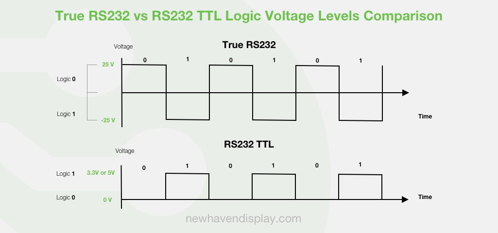
RS232 logic voltage levels
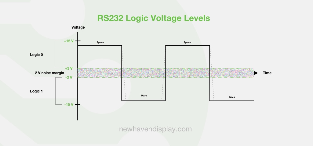
A true RS232 standard does not use TTL voltage levels (5V for logic 1 and 0V for logic 0). Instead, the original standard specifies -5V to -15V for a low level (space) and +5V to +15V for a high level (mark). Version EIA/TIA-232-D incremented the voltage range to ± 25V.
Taking the 2V noise margin into account, a low level (-3V to -15V) is defined as a logic 1 (marking), and a high level (+3V to +15V) is defined as a logic 0 (spacing).
Learn more: How to protect against ESD (Electrostatic Discharge)
The max slew rate is 30V/µs, and the max data rate using the 50 ft max cable length is 20kbps to avoid crosstalk between adjacent signals. The impedance between the driver and receiver is specified between 3kΩ and 7kΩ.
RS232 TTL
RS232 TTL is a term used to refer to a type of serial communication protocol that uses RS232-type specifications but with logic signals compatible with TTL (transistor-transistor logic) circuits. The voltage levels of TTL serial communication always stay between 0V (logic 0) and Vcc (logic 1, which is typically 3.3V or 5V).
While true RS-232 is not used as widely as it once was, the RS-232 TTL variant is still in use in applications where its lower voltage levels and signal compatibility with microcontrollers are needed. Many of our products at Newhaven Display are compatible with RS232 TTL serial communication.
Communication between a true RS232 and TTL is possible through a device capable of inverting the logic signals and regulating the signal voltage levels. The MAX232 integrated circuit is a popular solution to handle the voltage converting and inverting issues when communication between true RS232 and TTL is needed.
RS232 Functional Characteristics
The RS232 standard defines the functions of the signals. Although the standard defines plenty of functional signals, including a primary and secondary communications channel, few applications need or require all of these signals.
The RS232 standard interface signals can be divided into 4 categories:
- Data lines
- Control lines
- Timing lines
- Secondary functions
RS232 Signal Pins - Complete Function of Signals
| Signal Mnemonic | Signal Name | Direction DTE ⇔ DCE |
Signal Type |
|---|---|---|---|
| AB | Signal Common | — | Common |
| BA | Transmitted Data (TD) | ⇒ | Data |
| BB | Received Data (RD) | ⇐ | Data |
| CA | Request to Send (RTS) | ⇒ | Control |
| CB | Clear to Send (CTS) | ⇐ | Control |
| CC | Data Set Ready (DSR) | ⇐ | Control |
| CD | Data Terminal Ready (DTR) | ⇒ | Control |
| CE | Ring Indicator (RI) | ⇐ | Control |
| CF | Data Carrier Detect (DCD) | ⇐ | Control |
| CG | Signal Quality Detect (SQ) | ⇐ | Control |
| CH | Data Signal Rate Selector from DTE | ⇒ | Control |
| CI | Data Signal Rate Selector from DCE | ⇐ | Control |
| CJ | Ready for Receiving | ⇒ | Control |
| RL | Remote Loopback | ⇒ | Control |
| LL | Local Loopback | ⇒ | Control |
| TM | Test Mode | ⇐ | Control |
| DA | Transmitter Clock from DTE | ⇒ | Timing |
| DB | Transmitter Clock from DCE | ⇐ | Timing |
| DD | Receiver Clock from DCE | ⇐ | Timing |
| SBA | Secondary Transmitted Data S(TD) | ⇒ | Data |
| SBA | Secondary Received Data S(RD) | ⇐ | Data |
| SCA | Secondary Request to Send S(RTS) | ⇒ | Control |
| SCB | Secondary Clear to Send S(CTS) | ⇐ | Control |
| SCB | Secondary Data Carrier Detect S(DCD) | ⇐ | Control |
Mechanical Characteristics
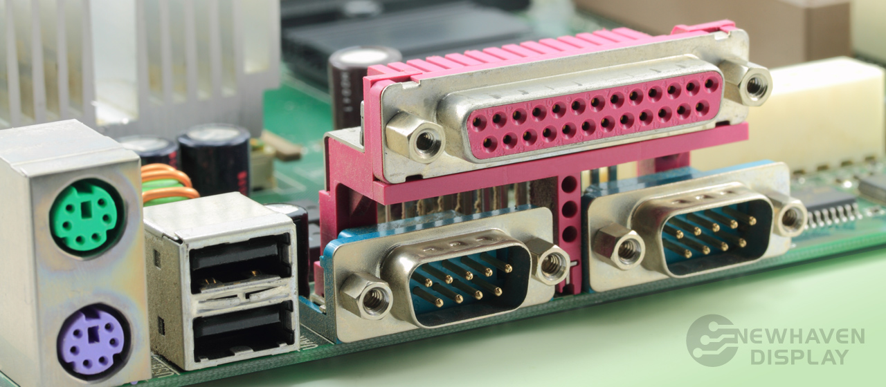
RS232 defines a 25-pin connector as the minimum connector size in order to support all the functional signals. DTE equipment utilizes a female housing for the connector and a male housing for the connection pins. DCE equipment utilizes male for the connector housing and female for the connection pins.
Because most applications do not require all specified signals, a 25-pin connector is rarely used due to its larger size. Instead, smaller D-miniature connectors, such as the DB-9, are commonly used.
RS232 Uses and Examples
RS232 is no longer the primary standard across consumer products due to existing newer and more advanced technologies like USB. However, the RS232 standard is still used in industrial and commercial applications with simple serial data communication requirements, such as industrial controls, automation equipment, network communications, robotics, and medical equipment.
RS232 Examples
- Interface between an LCD and a module.
- Interface between CNC machines and control systems.
- Communication between a computer (DTE) and a modem (DCE).
- Interface between a PLC (Programmable Logic Controller) and a module.
- Communication between a printer and a modem.
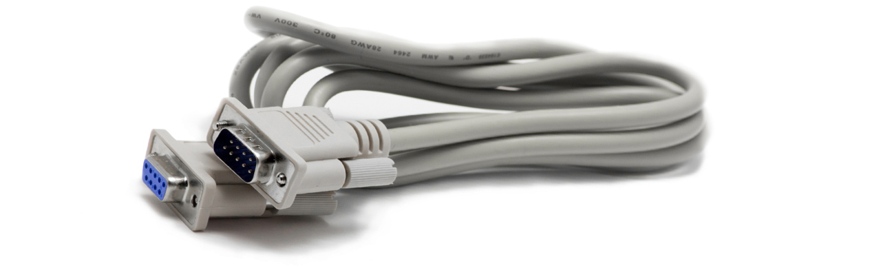
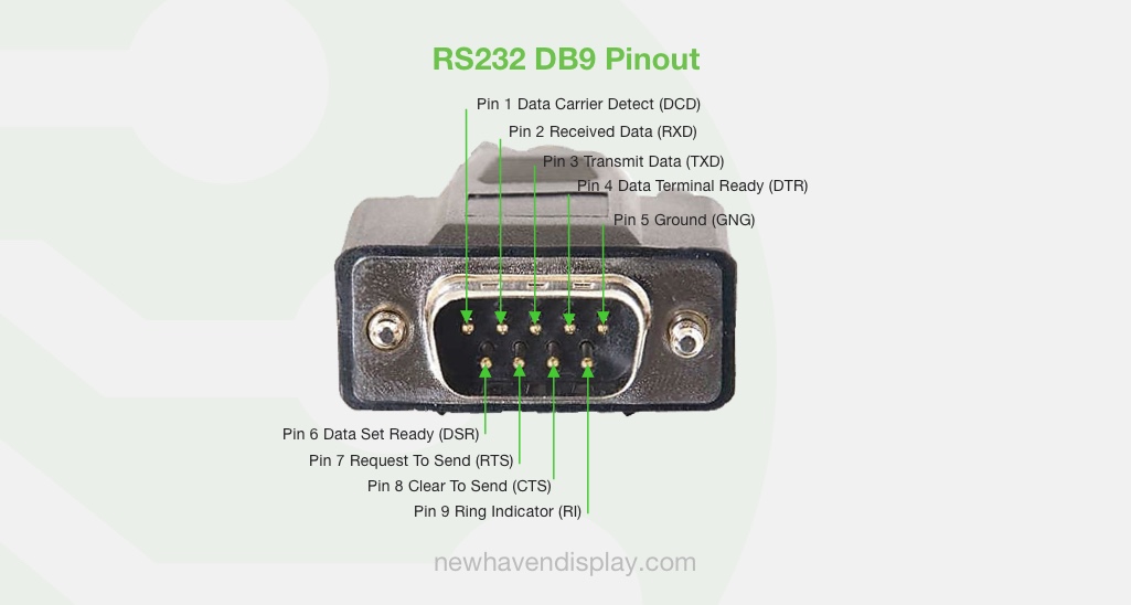
A typical example of the RS232 standard is the serial communication between a computer (DTE equipment) and a modem (DCE equipment) using a DB9 cable.
DB9 Male Cable Pinout
Did you know?
The D-subminiature connectors, like the DB-9, begin with the letter D because of its D-shaped metal shield. The letter after the D denotes the shell size.
RS-232 Advantages and Disadvantages
RS232 is a low-cost serial interface compatible with many new and legacy devices, is easy to implement, has simplified wiring, and has good immunity to EMI. Some of the RS232 disadvantages are low data communication speeds, negative and positive signal voltages can complicate power supply design, limited to single master and single slave, and its unbalanced transmission can be prone to noise.
RS-232 Advantages
- Low cost.
- Simplified wiring.
- Widely available.
- Good immunity to EMI.
RS-232 Disadvantages
- Low data communication speed - 20 kb per second.
- Limited to short distances - Works well for distances under 50 ft (15 meters).
- The requirement for positive and negative signal voltage increases the interface's power consumption and complicates power supply design.
- Unbalanced transmission.
Conclusion
RS232 is an excellent choice for applications requiring simple, low-speed serial communication. Although the original purpose of the standard was to connect a terminal with a modem, it has been used beyond the scope of its original purpose due to its simplicity and relatively low cost.

Latest Blog Posts
-

A Guide to TFT Display Interfaces
Display interfaces often get less attention than screen resolution or brightness, but they carry jus …Dec 16th 2025 -

Choosing the Right Display Resolution: A User-Friendly Guide
Display resolution is one of the most defining choices in product interface design. It determines ho …Dec 11th 2025 -

Arduino vs Raspberry Pi vs BeagleBone: Key Features and Differences
If you're working on an electronics project—whether it's for a DIY automated device, a digital sign, …Dec 8th 2025