
US2066 Tutorial: Character OLED with Arduino
Jul 30th 2024
If you are interested in getting started with character OLED displays using the US2066 controller chip, then you are in the right place. The all-in-one chip, US2066, simplifies driving OLED displays, making it easy for anyone to get started regardless of their skill level. Whether you're working on portable devices, industrial instruments, or anything in between, this guide will give you the knowledge you need to unlock the full potential of OLED displays with the US2066 controller.
I den här artikeln:
Tutorial Overview
In this tutorial, we will explore and highlight some key features of the US2066 OLED controller. We will also cover how to wire the display and provide example code to help you get started setting up your OLED with Arduino, including how to display text, adjust contrast, and perform character shifting.
The US2066 controller is at the heart of a wide range of our OLED displays. Currently, we offer several OLED displays using the US2066 controller, available in sizes from 2x16, 2x20, to 4x20, and in various monochrome colors.
OLED displays offer several advantages over traditional LCDs, including:
- Sharp, vivid visuals with high contrast ratios.
- Consistent image quality from wide viewing angles.
- Performance in various environments due to their wide temperature range.
- Lower power consumption, especially with dark colors.
- Superior refresh rates for smoother visuals with minimal motion blur.
- Thin, lightweight profile.
- Superior color accuracy and a wider color gamut for a vibrant viewing experience.
Expand Your Knowledge
Here are some resources related to some concepts in this tutorial:
Things You Will Need
- Arduino UNO Board
- 4x20 Character Slim OLED - NHD-0420CW-AB3 (can be purchased with pre-soldered pins)
- Jumper wires
- Arduino IDE software
- 1x20 Single Row Pin Header Connector (optional if the OLED is purchased with pre-soldered pins)
- Breadboard (optional)
You can also follow this tutorial with any similar OLED that has the US2066 controller.
Tutorial Resources
- 4x20 Character OLED product details
- 4x20 Character OLED product datasheet
- US2066 controller datasheet
- Download Arduino IDE
US2066 Controller Overview: An OLED Display IC Controller
The US2066 is a single-chip integrated circuit (IC) that simplifies driving small OLED displays. This compact and efficient solution delivers sharp visuals with high contrast, all while minimizing power consumption – ideal for battery-powered devices. But the US2066 offers more than just portability. Its versatility extends to a range of resolutions, power options, and interfaces (including I2C, SPI, and Parallel). This flexibility makes it suitable for applications beyond wearables and industrial displays.
US2066 Features
- Single-chip design.
- Features a built-in oscillator.
- Supports various display resolutions: 1, 2, 3, or 4 lines with 5x8 or 6x8 dots format.
- Supports multiple interfaces (I2C, SPI, and 4 / 8-bit 6800/8080 parallel).
- Low power consumption and flexible power options.
- 256-step contrast control.
- Selectable duty cycle (1/8, 1/16, 1/24, 1/32).
- Supports custom characters.
- Software selectable character sets.
- Row and column remapping.
- Double-height font characters.
- All characters reverse display.
- Enables text scrolling in both left and right directions.
- Independent line scrolling.
- Screen saving fade in/out feature.
- Allows all of the characters on the OLED display to be inverted.
- When power is applied, it automatically resets to ensure it's always in a known state.
- Supports screen saving fade in/out features.
- Features programmable frame frequency.
- Includes a smart crosstalk compensation scheme to reduce crosstalk between pixels.
- Operates in a wide range of operating temperatures: -40°C to 85°C.
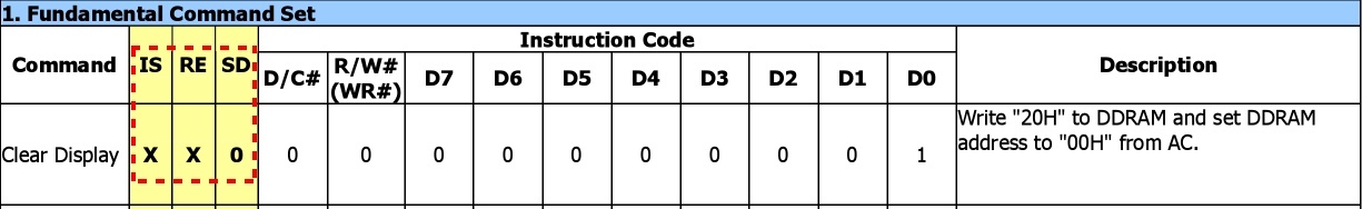
US2066 Command Tables
The US2066 controller features three different command sets, each providing different functions and control options for the OLED display:
- Fundamental Command Set: This set includes basic commands for display control, such as clearing the display, setting cursor position, and controlling display ON/OFF state.
- Extended Command Set: These commands extend the functionality of the display, allowing for features such as bi-directional shifting and adjusting display modes.
- OLED Command Set: Specific to OLED control, this set includes commands for adjusting contrast, enabling/disabling scrolling, and configuring display characteristics.
The command sets can be accessed by setting the logic bits IS, RE, and SD accordingly. Each command in the tables specifies how these bits must be set to ensure proper configuration.
For more information about the US2066 controller, you can view and download its datasheet from our support center here.
Wiring Schematic and Diagram
Let's start by wiring things up!
- A0 to A2 (Arduino) to pins 17 to 19 (OLED): Interface selection (we'll set it to parallel via code).
- D0 to D7 (Arduino) to pins 7 to 14 (OLED): Data lines.
- D8 (Arduino) to pin 4 (OLED): Data/Command select signal.
- D9 (Arduino) to pin 5 (OLED): Read/Write select signal.
- D10 (Arduino) to pin 6 (OLED): Enable signal.
- D11 (Arduino) to pin 15 (OLED): Chip select signal.
- D12 (Arduino) to pin 16 (OLED): Reset signal.
Make sure to also connect the OLED's ground (GND) and 3.3V power supply to the Arduino UNO.
OLED to Arduino UNO Schematic

Character Slim OLED to Arduino UNO Diagram
The Tinkercad diagram below provides a more visual representation to help with the wiring connections.

Character OLED - Arduino UNO Example Code
Using the US2066 controller in 8-bit 8080 parallel interface mode, the following code initializes and interfaces an Arduino Uno with an OLED display.
/*
* Newhaven Display invests time and resources providing this open source code,
* Please support Newhaven Display by purchasing products from Newhaven Display!
*
* This code is provided as an example only and without any warranty by Newhaven Display.
* Newhaven Display accepts no responsibility for any issues resulting from its use.
* The developer on the final application incorporating any parts of this
* sample code is responsible for ensuring its safe and correct operation
* and for any consequences resulting from its use.
* See the GNU General Public License for more details.
* Pin setup (Uses 3.3V Arduino Uno in 8-bit 8080 mode): DB0-DB7 connected to PORT D on UNO
*------------------------------
* Arduino        OLED Board   |
* GND          1  (VSS)       |
* 3.3V         2  (VDD)       |
* GND          3  (REGVDD)    |
* 8            4  (DC)        |
* 9            5  (WR)        |
* 10           6  (RD)        |
* 0            7  (DB0)       |
* 1            8  (DB1)       |
* 2            9  (DB2)       |
* 3            10 (DB3)       |
* 4            11 (DB4)       |
* 5            12 (DB5)       |
* 6            13 (DB6)       |
* 7            14 (DB7)       |
* 11           15 (CS)        |
* 12           16 (RES)       |
* A0           17 (BS0)       |
* A1           18 (BS1)       |
* A2           19 (BS2)       |
* GND          20 (VSS)       |
*------------------------------
*/
#define DC   8       //DC pin connected to Arduino digital pin 8
#define WR   9       //WR pin connected to Arduino digital pin 9
#define RD   10      //RD pin connected to Arduino digital pin 10
#define CS   11      //CS pin connected to Arduino digital pin 11
#define RES  12      //RES pin connected to Arduino digital pin 12
#define BS0  A0      //BS0 pin connected to Arduino Analog pin A0
#define BS1  A1      //BS1 pin connected to Arduino Analog pin A1
#define BS2  A2      //BS2 pin connected to Arduino Analog pin A2
void Init_OLED(){
  delay(1);
  Command(0x2A);     // Function set (extended Command set)
  Command(0x71);     // Function selection A
  Data(0x00);        // Disable internal VDD regulator for 3.3V application
  Command(0x28);     // Function set (fundamental Command set)
  Command(0x08);     // Display off, cursor off, blink off
  Command(0x2A);     // Function set (extended Command set)
  Command(0x79);     // OLED Command set enabled
  Command(0xD5);     // Set display clock divide ratio/oscillator frequency
  Command(0x70);     // Set display clock divide ratio/oscillator frequency
  Command(0x78);     // OLED Command set disabled
  Command(0x09);     // extended function set (4‐lines)
  Command(0x06);     // COM SEG direction
  Command(0x72);     // function selection B
  Data(0x03);        // ROM CGRAM selection
  Command(0x79);     // OLED Command set enabled
  Command(0xDA);     // Set SEG pins hardware configuration
  Command(0x10);     // Set SEG pins hardware configuration
  Command(0xDC);     // Function selection C
  Command(0x00);     // Function selection C
  Command(0x81);     // Set contrast control
  Command(0x7F);     // Set contrast control
  Command(0xD9);     // Set phase length
  Command(0xF1);     // Set phase length
  Command(0xDB);     // Set VCOMH deselect level
  Command(0x40);     // Set VCOMH deselect level
  Command(0x78);     // OLED Command set disabled
  Command(0x28);     // Function set (fundamental Command set)
  Command(0x01);     // Clear display
  delay(10);
  Command(0x80);     // Set DDRAM address to 0x00
  Command(0x0C);     // Display ON
  delay(10);
}
void Command(unsigned char c){  // To send Commands
  PORTD=c;
  digitalWrite(DC,LOW);         // DC set to HIGH for Data
  delay(1);
  digitalWrite(WR,LOW);         // WR set to LOW for latching
  delay(1);
  digitalWrite(WR,HIGH);        // WR set to HIGH for latching
  delay(1);
}
void Data(unsigned char d){     // To send Data
  PORTD=d;
  digitalWrite(DC,HIGH);        // DC set to HIGH for Data
  delay(1);
  digitalWrite(WR,LOW);         // WR set to LOW for latching
  delay(1);
  digitalWrite(WR,HIGH);        // WR set to HIGH for latching
  delay(1);
}
void Set_contrast(unsigned char d){
Command(0x2A);                  // Set RE=1
Command(0x79);                  // Set SD=1
Command(0x81);                  // Set Contrast command
Command(d);                     // Contrast level data
Command(0x78);                  // Set SD=0
Command(0x28);                  // Set RE=0
}
void Set_Scroll(int x){
Command(0x2A);                  // Set RE=1
Command(0x11);                  // Set DH' bit to enable shift
Command(0x28);                  // Set RE=0
Command(0x29);                  // Set IS=1
Command(0x2A);                  // Set RE=1
Command(0x1F);                  // Set lines to shift
Command(0x28);                  // Set RE=0 and IS=0
for(int i=0;i<x;i++){
  Command(0x1C);                // Shift right
  delay(130);                   // Control speed of shift
 }
}
void text1(){
Command(0xC0);                   // Brings The Cursor to Home Position
Command(0x80);                   // Clear Screen
for(int i=0; i<4;i++){
Data(0x20);              //Space
Data(0x4E);              //N
Data(0x65);              //e
Data(0x77);              //w
Data(0x68);              //H
Data(0x61);              //a
Data(0x76);              //v
Data(0x65);              //e
Data(0x6E);              //n
Data(0x20);              //Space
Data(0x44);              //D
Data(0x69);              //i
Data(0x73);              //s
Data(0x70);              //p
Data(0x6C);              //l
Data(0x61);              //a
Data(0x79);              //y
Data(0x21);              //!
Data(0x20);              //Space
Data(0x20);              //Space
}
}
void setup() {
  DDRD=0xFF;                       // Set PORTD as output
  DDRB=0xFF;                       // Set PORTB as output
  pinMode(BS0,OUTPUT);
  pinMode(BS1,OUTPUT);             // Interface selection pins
  pinMode(BS2,OUTPUT);
  digitalWrite(CS,LOW);            // CS Active LOW
  digitalWrite(RES,HIGH);          // Set RES HIGH
  digitalWrite(RD,HIGH);           // Set READ HIGH
  digitalWrite(BS0,LOW);
  digitalWrite(BS1,HIGH);          // 8080 8-bit Parallel interface
  digitalWrite(BS2,HIGH);
  Init_OLED();                     // Initialize OLED
  text1();                         // Display text
  delay(1200);
}
void loop() {
  Set_Scroll(20);                  // Shift display one full rotation (20 Characters)
  delay(1000);
  Set_contrast(0x00);              // Set contrast Min
  delay(1200);
  Set_contrast(0x3C);              // Set contrast Medium
  delay(1200);
  Set_contrast(0xFF);              // Set contrast Max
  delay(1200);
}
Although the comments in the code are helpful, here is a brief explanation of what this code does:
Pin Definitions: The code defines the pins used for communication between the Arduino and the OLED display, including DC (Data/Command), write, read, chip select, reset, and bus interface selection pins.
OLED Initialization: The Init_OLED function initializes the OLED display by sending a sequence of commands to configure the display settings such as contrast, display mode, and clock frequency.
Command and Data Functions: The Command and Data functions are used to send commands and data to the OLED display.
Contrast Adjustment: The Set_contrast function allows for adjusting the display contrast by sending the appropriate commands and data.
Text Scrolling: The Set_Scroll function enables text shifting on the display, providing a way to scroll text across the screen.
Text Display: The text1 function is responsible for writing the text "Newhaven Display!" to the OLED display by bringing the cursor to the home position with Command(0xC0);, clearing the screen with Command(0x80);, and using a loop to ensure the text is written four times, once for each row of the display.
Arduino Setup and Loop: The setup function configures the Arduino's ports and initializes the OLED display, while the loop function continuously demonstrates the scrolling and contrast adjustment features.
OLED Contrast Adjustment Process
The flowchart below outlines the steps to adjust the contrast on an OLED display using specific commands. The procedure involves switching to an extended command set, enabling OLED-specific commands, setting the desired contrast level, and then resetting to the standard command set.

OLED Character Shifting / Scrolling Effect
The flowchart below illustrates how to enable character shifting (scrolling effect) on the OLED display. The process includes toggling between command sets, activating shift modes, configuring shift parameters, and executing the shift with controlled timing.

Instructions to Upload and Run the Code
- Open Arduino IDE: Launch the Arduino Integrated Development Environment (IDE) on your computer.
- Create a New Sketch: Go to
File > Newto open a new sketch. - Copy and Paste the Code: Copy the entire code above and paste it into the new sketch.
- Save the Sketch: Save the sketch by going to
File > Save. - Connect Your Arduino: Plug your Arduino Uno into your computer using a USB cable.
- Select Your Board and Port:
- Go to
Tools > Boardand select "Arduino Uno". - Go to
Tools > Portand select the port that your Arduino is connected to.
- Go to
- Upload the Code: Click the upload button (right arrow icon) in the Arduino IDE toolbar to compile and upload the code to your Arduino Uno.
- Run the Code: Once the upload is complete, the code will automatically run on your Arduino. You should see the OLED display initialize and display the sample text, along with the contrast adjustment and text scrolling features.
Läs mer
For more tutorials and insights, check out other tutorials:
Troubleshooting Tips
- Verify your wiring: Incorrect wiring is one of the most common issues when troubleshooting. Verify your jumper cables are connected to the correct pins by following the wiring diagram provided. If you have access to a multimeter, you can also verify continuity between the pins (with the power off). Jumper cables can go bad, so even when properly wired, you may still not get a proper connection.
- Reset or Reflash the Arduino: You can also try resetting the Arduino using the reset button or doing a power cycle. Note that interrupting the Arduino flashing process can cause the program to corrupt. When uploading a program to your Arduino, do not unplug the device until you see a "Done Uploading" message.
- Check Pin Voltages: If you have access to a multimeter, use it to check if your VDD pin is receiving the proper voltage (3.3V). You can also check your interface pins to make sure these are being set High or Low properly (use the display datasheet for interface options).
- Power supply: In some cases, powering the Arduino through the programming cable won’t provide enough power. Try using the DC jack with an appropriate power supply (7-12V).
- Check for Physical Damage: Inspect the OLED display for any physical damage like broken pins or traces.
- Verify Code: If any modifications are made to the code, verify they have been done properly. When using specific commands from the multiple command tables, verify that you are returning to the main command table (Fundamental Command Set) before attempting to send data to the display.
- Different Arduino Models: If you are trying to implement this code with a different model Arduino, verify the logic level is 3.3V. You may also have to change any calls to specific ports within the code since these vary from model to model.
Slutsats
The single-chip US2066 controller provides a simple and efficient way to integrate high-quality visuals with excellent features for many character OLED applications. This tutorial offered an easy way to get you started, but the US2066 offers a wide range of features beyond what was covered here. We encourage you to explore the capabilities of this controller to create some amazing visuals for your projects.