Come collegare l'LCD ad Arduino
19 maggio 2023
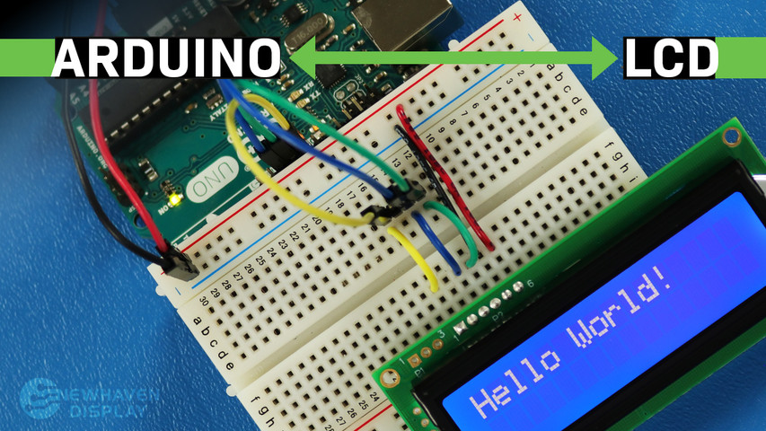
Il display LCD (Liquid Crystal Display) è un display comunemente utilizzato nei progetti Arduino, poiché offre un modo semplice per visualizzare informazioni all'utente, come testo e caratteri di base. È un display utile sia per i principianti che per gli utenti esperti ed è in genere uno dei primi display che le persone utilizzano quando iniziano a utilizzare una scheda Arduino.
Questo tutorial ti mostrerà come collegare e interagire tra un display LCD a caratteri 16x2 e una scheda Arduino UNO utilizzando la comunicazione seriale.
I principi illustrati in questo tutorial possono essere applicati anche ad altri display LCD e altre schede di sviluppo. Iniziamo!
LCD - Tutorial Arduino - Indice
- Hardware e strumenti necessari
- Pinout LCD
- Pinout Arduino
- Circuito - schema di collegamento e schema elettrico per la comunicazione SPI
- Codice di esempio che utilizza l'interfaccia SPI
- Ciao mondo!
- Visualizza il testo sulla prima e sulla seconda riga
- Visualizza testo lungo
- Blink - Visualizza il testo con un cursore lampeggiante
- Cursore + scorrimento automatico del testo
- Testo a scorrimento automatico
- Regolazione del contrasto dello schermo LCD
- Come utilizzare la retroilluminazione LCD
- Tabelle dei caratteri/font
- Circuito - schema di collegamento e schema elettrico per comunicazione RS232 TTL
- Ciao mondo! Codice di esempio che utilizza l'interfaccia RS232 TTL
- Risoluzione dei problemi del tuo LCD - Progetto Arduino
- Risorse aggiuntive
Hardware e strumenti necessari
Gli LCD sono disponibili in varie dimensioni e configurazioni, ma il più comunemente usato è quello da 16x2. Ha 2 righe che possono contenere 16 caratteri ciascuna.
Utilizzeremo il display Newhaven 16x2 con codice NHD-0216K3Z-NSW-BBW-V3, che ha un microcontrollore PIC16F690 integrato. Questo LCD supporta tre interfacce seriali: I2C, SPI e RS-232 (TTL). Questo articolo si concentrerà sulle interfacce SPI e RS-232 e fornirà esempi di codice per entrambe.
Questo display è disponibile per l'acquisto qui. La scheda tecnica e le specifiche del prodotto possono essere visualizzate o scaricate qui.
Si prega di notare che l'utilizzo dell'interfaccia SPI richiede la saldatura di un resistore al display, mentre l'interfaccia RS-232 TTL non lo richiede. Pertanto, se si preferisce seguire questo tutorial senza saldare il resistore, è possibile seguire le istruzioni relative all'interfaccia RS-232 TTL e la sezione con gli esempi di codice.
Cosa ti serve per collegare Arduino a un LCD
- LCD 16x2
- Connettore a pin a fila singola
- Arduino UNO
- messa a punto
- Fili di ponticello
- Saldatore e stagno
- Cavo USB da maschio A a maschio B (cavo per stampante)
- IDE Arduino
- Resistenza da 0 ohm (opzionale - solo per comunicazione SPI)
Ti consigliamo di leggere il nostro articolo sul blog Come proteggere i dispositivi elettronici dall'ESD prima di immergerti in questo tutorial, soprattutto se sei un principiante nel campo dell'elettronica.
Pinout LCD 16x2
Il display LCD Newhaven 16x2 offre un modo semplice per interagire con la scheda Arduino UNO utilizzando la comunicazione seriale. I pin sulla porta P1 sono progettati specificamente per la comunicazione seriale RS232 TTL, mentre i pin sulla porta P2 sono destinati alla comunicazione seriale I2C e SPI.
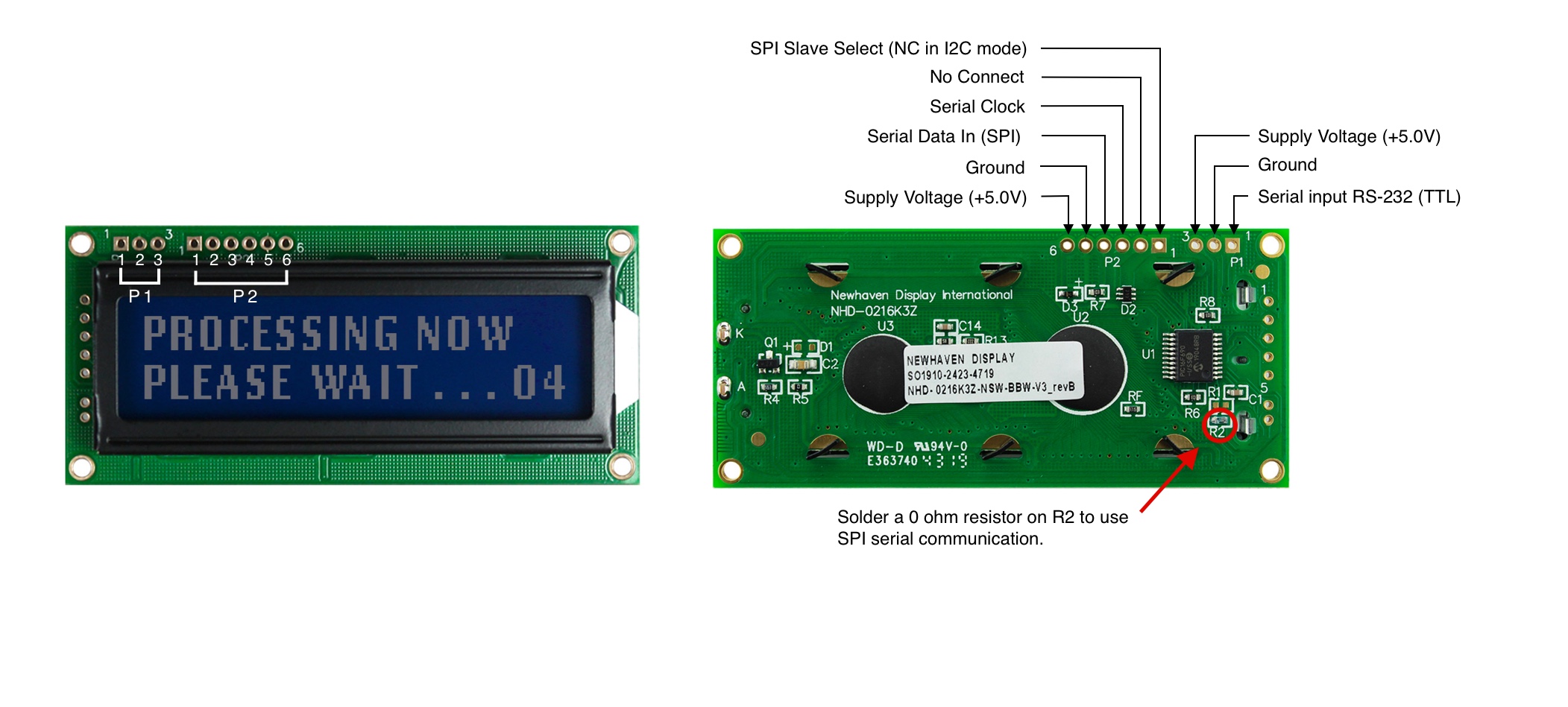
Descrizione pin P1 - Comunicazione RS232 TTL
| Numero di pin | Simbolo | Descrizione della funzione |
|---|---|---|
| 1 | RX | Ingresso seriale RS-232 (TTL) |
| 2 | V SS | Terreno |
| 3 | V DD | Tensione di alimentazione (+5,0 V) |
Descrizione dei pin P2 - Comunicazione SPI e I2C
| Numero di pin | Simbolo | Descrizione della funzione |
|---|---|---|
| 1 | SPISS | Selezione slave SPI (NC in modalità I2C) |
| 2 | SDO | Nessuna connessione |
| 3 | SCK/SCL | Orologio seriale |
| 4 | SDI/SDA | Dati seriali in ingresso (SPI) / Dati seriali (I2C) |
| 5 | V SS | Terreno |
| 6 | V DD | Tensione di alimentazione (+5,0 V) |
Le specifiche complete relative alla piedinatura LCD sono disponibili qui.
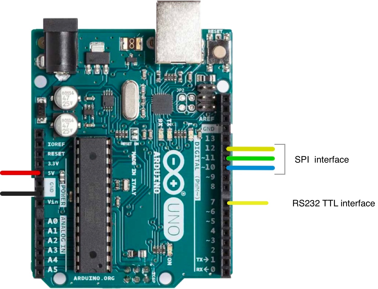
Pinout Arduino
La scheda Arduino UNO dispone di 20 pin di ingresso/uscita, inclusi 14 pin digitali e 6 pin analogici. Per questo progetto utilizzeremo i pin 5V e GND dai segnali di alimentazione, i pin 10, 11 e 12 per SPI o I2C e il pin 7 per RS232 TTL.
Lo schema completo della piedinatura di Arduino UNO è disponibile qui.
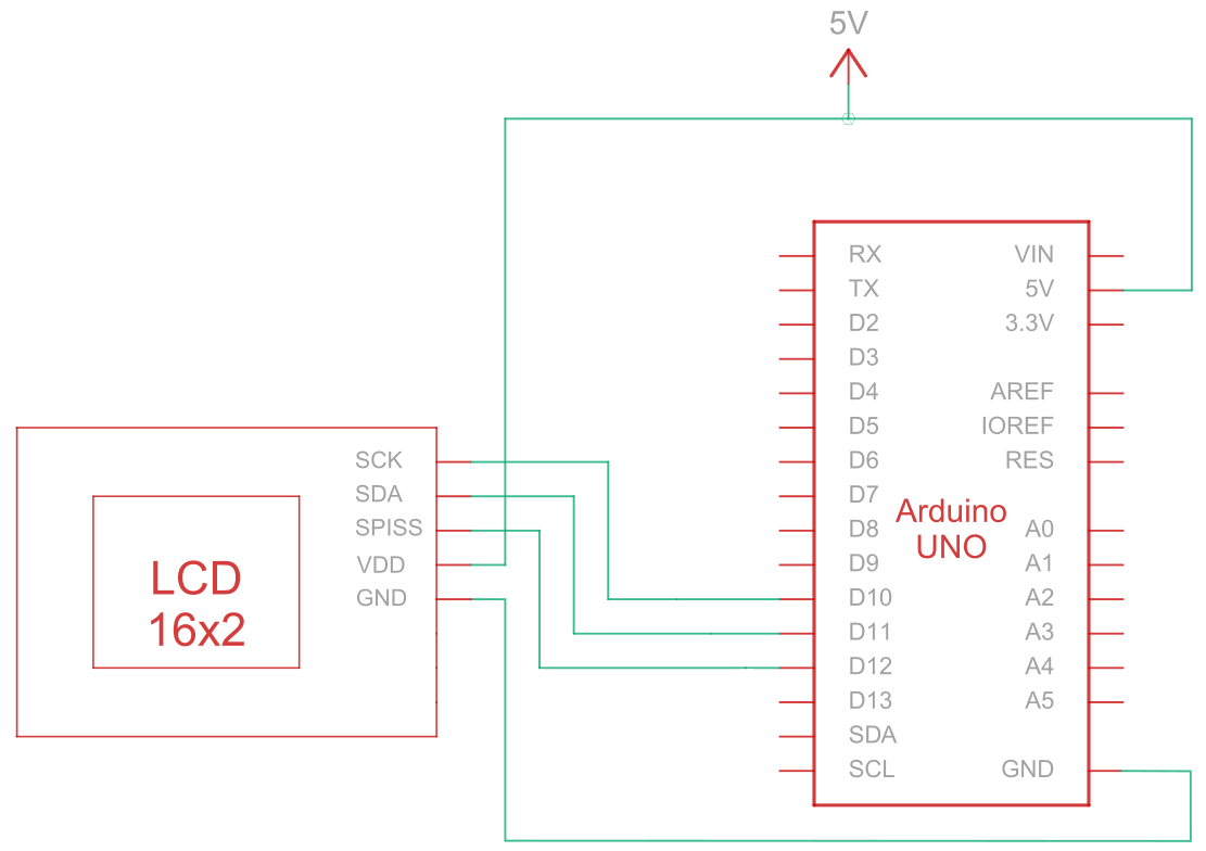
Circuito - Schema di collegamento e schema elettrico per la comunicazione SPI
L'interfaccia seriale periferica (SPI) è un bus di comunicazione seriale sincrono utilizzato per comunicazioni a breve distanza e ad alta velocità tra più dispositivi. Il circuito di connessione per la comunicazione SPI tra Arduino (dispositivo master) e LCD (dispositivo slave) utilizza cinque fili per comunicare, come descritto nella tabella seguente:
| Arduino | LCD | Tipo di connessione |
|---|---|---|
| Pin 5V | Pin 6: V DD | Potenza |
| Perno di terra | Pin 5: Terra | Terreno |
| Pin 10: Selezione slave | Pin 3: SCK/SCL | Orologio seriale |
| Pin 11: MISO | Pin 4: Ingresso dati seriali (SPI) / Dati seriali (I2C) | Dati seriali in entrata |
| Pin 12: MOSI | Pin 1: SPISS | Selezione slave SPI |
Nota:
Per abilitare SPI è necessario che R1 sia aperto e R2 sia accorciato come specificato nella scheda tecnica. Inoltre, prima di iniziare, assicurarsi che Arduino sia spento durante il cablaggio del circuito.
Circuito di cablaggio SPI
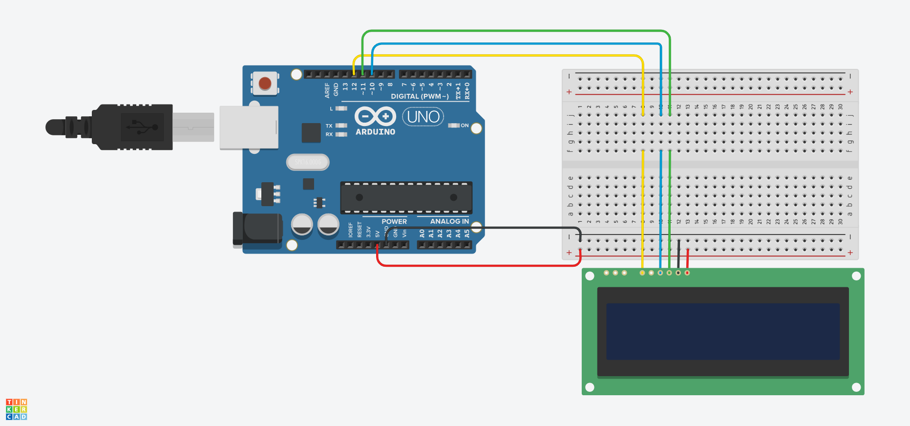
Schema di cablaggio SPI
Arduino - Codice di esempio LCD utilizzando l'interfaccia SPI
I seguenti esempi di codice mostrano come utilizzare la comunicazione seriale tra Arduino e un LCD a 16x2 caratteri utilizzando l'interfaccia SPI. Troverete commenti utili negli esempi di codice, ma analizziamo alcune delle funzioni riportate di seguito:
- Il
SPI_Out()La funzione invia comandi e dati al display LCD tramite SPI. Lo fa iterando attraverso gli 8 bit del byte di input e inviando il valore di ciascun bit al display LCD. - Il
Imposta_Pin()La funzione configura i pin SPI come pin di uscita. - Il
Imposta_Contrasto()La funzione imposta il contrasto del display LCD. - Il
Imposta_Retroilluminazione()La funzione imposta la retroilluminazione del display LCD. - Il
Clear_Display()La funzione cancella lo schermo LCD. - Il
Imposta_Cursore()La funzione abilita o disabilita il cursore lampeggiante sul display LCD, a seconda del parametro di input. - Il
impostare()La funzione è la funzione principale e viene eseguita una volta all'avvio di Arduino. Viene utilizzata per inizializzare le impostazioni, le variabili ed eseguire qualsiasi altra funzione e configurazione necessaria per il progetto. - Il
loop()La funzione viene eseguita in un ciclo continuo per tutta la durata dell'alimentazione della scheda Arduino. In alcuni esempi riportati di seguito, questa funzione è vuota e non esegue alcuna operazione, poiché è sufficiente eseguire alcune funzioni una sola volta.
Arduino - Esempi di codice LCD utilizzando SPI:
- Ciao mondo!
- Visualizza il testo sulla prima e sulla seconda riga
- Visualizza testo lungo
- Visualizza il testo con un cursore lampeggiante
- Cursore + scorrimento automatico del testo
- Scorrimento automatico
- Contrasto
- Retroilluminazione
- Tabelle dei caratteri/font
È possibile adattare ed espandere gli esempi di codice in base alle specifiche esigenze del proprio progetto basato su Arduino.
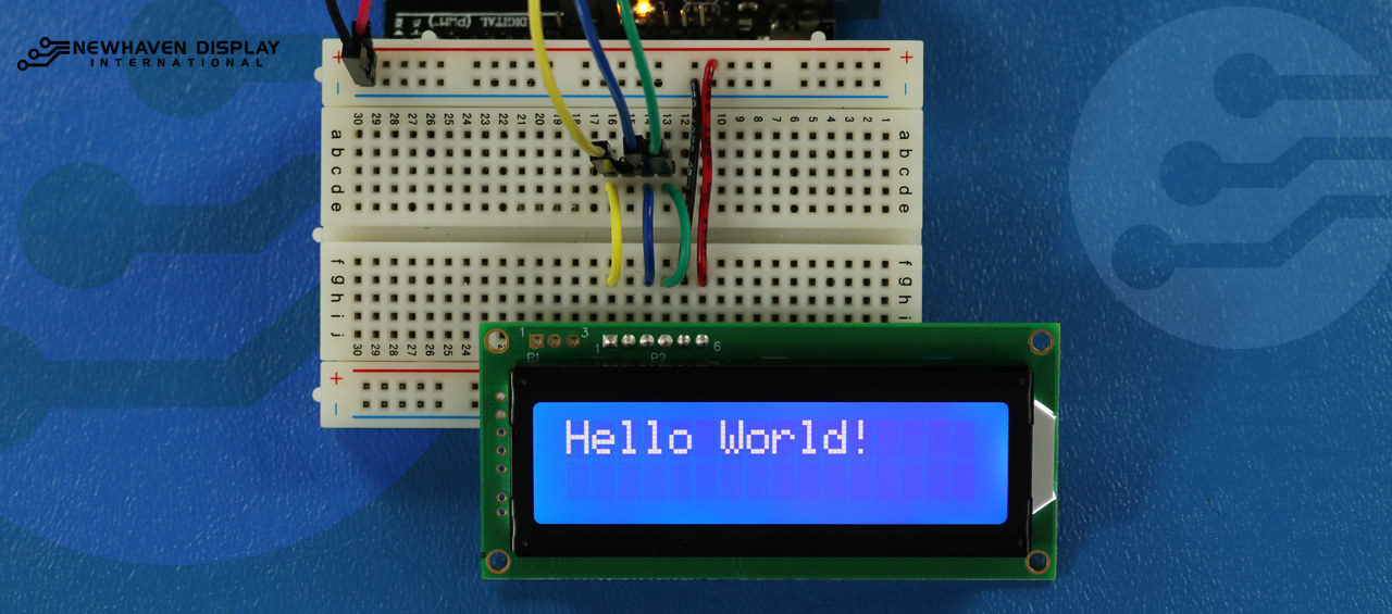
Ciao mondo!
Il seguente esempio di codice visualizza "Hello Word!" sul display LCD.
/*  SPI Wiring Reference for: NHD-0216K3Z-NSW-BBW-V3
  ---------------------------
  LCD         |   Arduino
  ---------------------------
  1(SPISS)  --> 12
  2(SDO)    --> No Connect
  3(SCK)    --> 10
  4(SDA)    --> 11
  5(VSS)    --> Ground
  6(VDD)    --> 5V
*/
/*****************************************************
   Arduino pin definition
  /*****************************************************/
#define SPISS_PIN   12
#define SDA_PIN     11
#define SCK_PIN     10
/*****************************************************
   SPI function to send command and data.
   For more information on SPI please visit our Support Center
  /*****************************************************/
void SPI_Out(unsigned char a) {
  digitalWrite(SPISS_PIN, LOW);
  for (int n = 0; n < 8; n++) {
    if ((a & 0x80) == 0x80) {
      digitalWrite(SDA_PIN, HIGH);
      delayMicroseconds(200);
    }
    else {
      digitalWrite(SDA_PIN, LOW);
    }
    delayMicroseconds(200);
    a = a << 1;
    digitalWrite(SCK_PIN, LOW);
    digitalWrite(SCK_PIN, HIGH);
    delayMicroseconds(200);
  }
  digitalWrite(SCK_PIN, HIGH);
  delayMicroseconds(200);
  digitalWrite(SPISS_PIN, HIGH);
}
/*****************************************************
   Set Arduino UNO IO ports as Output mode
  /*****************************************************/
void Set_Pins() {
  pinMode(SPISS_PIN, OUTPUT);
  pinMode(SCK_PIN, OUTPUT);
  pinMode(SDA_PIN, OUTPUT);
}
/*****************************************************
   Set LCD Contrast
  /*****************************************************/
void Set_Contrast() {
  SPI_Out(0xFE);              //prefix command
  SPI_Out(0x52);              //contrast command
  SPI_Out(0x28);              //set contrast value
  delayMicroseconds(500);
}
/*****************************************************
   Set LCD Backlight
  /*****************************************************/
void Set_Backlight() {
  SPI_Out(0xFE);             //prefix command
  SPI_Out(0x53);             //backlight command
  SPI_Out(0x08);             //set backlight value
  delayMicroseconds(100);
}
/*****************************************************
   Clear LCD
  /*****************************************************/
void Clear_Display() {
  SPI_Out(0xFE);             //prefix command
  SPI_Out(0x51);             //clear display command
  delayMicroseconds(1500);
}
/*****************************************************
   Set cursor
   Mode = 0 sets Blinking cursor off
   Mode = 1 sets Blinking cursor on
  /*****************************************************/
void Set_Cursor(int mode) {
  SPI_Out(0xfe);          //prefix command
  if (mode == 0) {
    SPI_Out(0x4c);        //Blinking cursor off
  }
  else if (mode == 1) {
    SPI_Out(0x4b);        //Blinking cursor on
  }
  delayMicroseconds(100);
}
/*****************************************************
   Write "Hello World!" to LCD
  /*****************************************************/
void Hello_World() {
  SPI_Out(0x48); // H
  SPI_Out(0x65); // E
  SPI_Out(0x6C); // l
  SPI_Out(0x6C); // l
  SPI_Out(0x6F); // o
  SPI_Out(0x11); // Blank
  SPI_Out(0x57); // W
  SPI_Out(0x6f); // o
  SPI_Out(0x72); // r
  SPI_Out(0x6c); // l
  SPI_Out(0x64); // d
  SPI_Out(0x21); // !
}
/*****************************************************
     Main function
  /*****************************************************/
void setup() {
  Set_Pins();         //set IO ports
  Set_Cursor(0);      //turns off blinking cursor
  Set_Contrast();     //set display contrast
  Set_Backlight();    //set display backlight
  Clear_Display();    //clear display
  Hello_World();      //display "Hello World!"
}
void loop() {
}
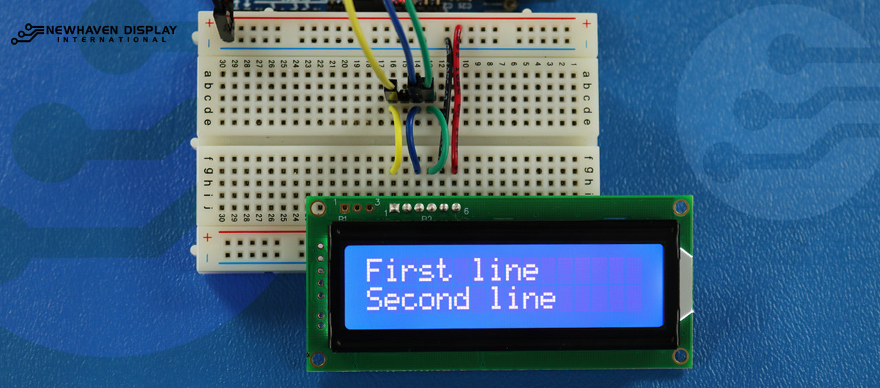
Visualizza il testo sulla prima e sulla seconda riga
Questo codice mostrerà il testo "Prima riga" nella prima riga e "Seconda riga" nella seconda riga.
/*****************************************************
  This code was written for the Arduino UNO using SPI Interface.
  This code displays text in row one and row two of LCD.
  /*  SPI Wiring Reference for: NHD-0216K3Z-NSW-BBW-V3
  ---------------------------
  LCD         |   Arduino
  ---------------------------
  1(SPISS)  --> 12
  2(SDO)    --> No Connect
  3(SCK)    --> 10
  4(SDA)    --> 11
  5(VSS)    --> Ground
  6(VDD)    --> 5V
*/
/*****************************************************
   Arduino pin definition
  /*****************************************************/
#define SPISS_PIN   12
#define SDA_PIN     11
#define SCK_PIN     10
/*****************************************************
   SPI function to send command and data.
   For more information on SPI please visit our Support Center
  /*****************************************************/
void SPI_Out(unsigned char a) {
  digitalWrite(SPISS_PIN, LOW);
  for (int n = 0; n < 8; n++) {
    if ((a & 0x80) == 0x80) {
      digitalWrite(SDA_PIN, HIGH);
      delayMicroseconds(200);
    }
    else {
      digitalWrite(SDA_PIN, LOW);
    }
    delayMicroseconds(200);
    a = a << 1;
    digitalWrite(SCK_PIN, LOW);
    digitalWrite(SCK_PIN, HIGH);
    delayMicroseconds(200);
  }
  digitalWrite(SCK_PIN, HIGH);
  delayMicroseconds(200);
  digitalWrite(SPISS_PIN, HIGH);
}
/*****************************************************
   Set Arduino UNO IO ports as Output mode
  /*****************************************************/
void Set_Pins() {
  pinMode(SPISS_PIN, OUTPUT);
  pinMode(SCK_PIN, OUTPUT);
  pinMode(SDA_PIN, OUTPUT);
}
/*****************************************************
   Set LCD Contrast
  /*****************************************************/
void Set_Contrast() {
  SPI_Out(0xFE);              //prefix command
  SPI_Out(0x52);              //contrast command
  SPI_Out(0x28);              //set contrast value
  delayMicroseconds(500);
}
/*****************************************************
   Set LCD Backlight
  /*****************************************************/
void Set_Backlight() {
  SPI_Out(0xFE);             //prefix command
  SPI_Out(0x53);             //backlight command
  SPI_Out(0x08);             //set backlight value
  delayMicroseconds(100);
}
/*****************************************************
   Clear LCD
  /*****************************************************/
void Clear_Display() {
  SPI_Out(0xFE);             //prefix command
  SPI_Out(0x51);             //clear display command
  delayMicroseconds(1500);
}
/*****************************************************
   Write "First Line" to row one on LCD
  /*****************************************************/
void Send_First_Line_Text() {
  SPI_Out(0x46); // F
  SPI_Out(0x69); // i
  SPI_Out(0x72); // r
  SPI_Out(0x73); // s
  SPI_Out(0x74); // t
  SPI_Out(0x20); // blank space
  SPI_Out(0x6c); // l
  SPI_Out(0x69); // i
  SPI_Out(0x6e); // n
  SPI_Out(0x65); // e
}
/*****************************************************
   Write "Second Line" to row two on LCD
  /*****************************************************/
void Send_Second_Line_Text() {
  SPI_Out(0x53); // S
  SPI_Out(0x65); // e
  SPI_Out(0x63); // c
  SPI_Out(0x6f); // o
  SPI_Out(0x6e); // n
  SPI_Out(0x64); // d
  SPI_Out(0x20); // blank space
  SPI_Out(0x6c); // l
  SPI_Out(0x69); // i
  SPI_Out(0x6e); // n
  SPI_Out(0x65); // e
}
/*****************************************************
   Set Row address
   Line = 1 sets for first row
   Line = 2 sets for second row
  /*****************************************************/
void Set_Row(int line) {
  SPI_Out(0xfe);      //prefix command
  SPI_Out(0x45);      //set cursor command
  if (line == 1) {
    SPI_Out(0x00);    //cursor position: row one, column one
  }
  else if (line == 2) {
    SPI_Out(0x40);    //cursor position: row two, column one
  }
  delayMicroseconds(100);
}
/*****************************************************
     Main function
  /*****************************************************/
void setup() {
  Set_Pins();         //set IO ports
  Set_Contrast();     //set display contrast
  Set_Backlight();    //set display backlight
  Clear_Display();    //clear display
  Set_Row(1);
  Send_First_Line_Text();       //writes to first line of display
  Set_Row(2);
  Send_Second_Line_Text();      //writes to second line of display
  delay(1000);
}
void loop() {
}
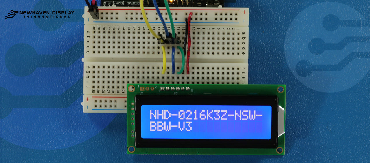
Visualizza testo lungo
Questo codice visualizza il testo che si estende alla seconda riga. Per questo esempio, visualizzeremo il testo "NHD-0216K3Z-NSW-BBW-V3".
/*****************************************************
  This code displays the part number: NHD-0216K3Z-NSW-BBW-V3.
  /*  SPI Wiring Reference for: NHD-0216K3Z-NSW-BBW-V3
  ---------------------------
  LCD         |   Arduino
  ---------------------------
  1(SPISS)  --> 12
  2(SDO)    --> No Connect
  3(SCK)    --> 10
  4(SDA)    --> 11
  5(VSS)    --> Ground
  6(VDD)    --> 5V
*/
/*****************************************************
   Arduino pin definition
  /*****************************************************/
#define SPISS_PIN   12
#define SDA_PIN     11
#define SCK_PIN     10
/*****************************************************
   SPI function to send command and data.
   For more information on SPI please visit our Support Center
  /*****************************************************/
void SPI_Out(unsigned char a) {
  digitalWrite(SPISS_PIN, LOW);
  for (int n = 0; n < 8; n++) {
    if ((a & 0x80) == 0x80) {
      digitalWrite(SDA_PIN, HIGH);
      delayMicroseconds(200);
    }
    else {
      digitalWrite(SDA_PIN, LOW);
    }
    delayMicroseconds(200);
    a = a << 1;
    digitalWrite(SCK_PIN, LOW);
    digitalWrite(SCK_PIN, HIGH);
    delayMicroseconds(200);
  }
  digitalWrite(SCK_PIN, HIGH);
  delayMicroseconds(200);
  digitalWrite(SPISS_PIN, HIGH);
}
/*****************************************************
   Set Arduino UNO IO ports as Output mode
  /*****************************************************/
void Set_Pins() {
  pinMode(SPISS_PIN, OUTPUT);
  pinMode(SCK_PIN, OUTPUT);
  pinMode(SDA_PIN, OUTPUT);
}
/*****************************************************
   Set LCD Contrast
  /*****************************************************/
void Set_Contrast() {
  SPI_Out(0xFE);              //prefix command
  SPI_Out(0x52);              //contrast command
  SPI_Out(0x28);              //set contrast value
  delayMicroseconds(500);
}
/*****************************************************
   Set LCD Backlight
  /*****************************************************/
void Set_Backlight() {
  SPI_Out(0xFE);             //prefix command
  SPI_Out(0x53);             //backlight command
  SPI_Out(0x08);             //set backlight value
  delayMicroseconds(100);
}
/*****************************************************
   Clear LCD
  /*****************************************************/
void Clear_Display() {
  SPI_Out(0xFE);             //prefix command
  SPI_Out(0x51);             //clear display command
  delayMicroseconds(1500);
}
/*****************************************************
   Set cursor
   Mode = 0 sets Blinking cursor off
   Mode = 1 sets Blinking cursor on
  /*****************************************************/
void Set_Cursor(int mode) {
  SPI_Out(0xfe);          //prefix command
  if (mode == 0) {
    SPI_Out(0x4c);        //Blinking cursor off
  }
  else if (mode == 1) {
    SPI_Out(0x4b);        //Blinking cursor on
  }
  delayMicroseconds(100);
}
/*****************************************************
   Set Row address
   Line = 1 sets for first row
   Line = 2 sets for second row
  /*****************************************************/
void Set_Row(int line) {
  SPI_Out(0xfe);      //prefix command
  SPI_Out(0x45);      //set cursor command
  if (line == 1) {
    SPI_Out(0x00);    //cursor position: row one, column one
  }
  else if (line == 2) {
    SPI_Out(0x40);    //cursor position: row two, column one
  }
  delayMicroseconds(100);
}
/*****************************************************
   Write "NHD-0216K3Z-NSW-BBW-V3" to LCD
  /*****************************************************/
void Part_Number() {
  Set_Row(1);
  SPI_Out(0x4e); // N
  SPI_Out(0x48); // H
  SPI_Out(0x44); // D
  SPI_Out(0xb0); // -
  SPI_Out(0x30); // 0
  SPI_Out(0x32); // 2
  SPI_Out(0x31); // 1
  SPI_Out(0x36); // 6
  SPI_Out(0x4b); // K
  SPI_Out(0x33); // 3
  SPI_Out(0x5a); // Z
  SPI_Out(0xb0); // -
  SPI_Out(0x4e); // N
  SPI_Out(0x53); // S
  SPI_Out(0x57); // W
  SPI_Out(0xb0); // -
  Set_Row(2);
  SPI_Out(0x42); // B
  SPI_Out(0x42); // B
  SPI_Out(0x57); // W
  SPI_Out(0xb0); // -
  SPI_Out(0x56); // V
  SPI_Out(0x33); // 3
}
/*****************************************************
     Main function
  /*****************************************************/
void setup() {
  Set_Pins();         //set IO ports
  Set_Cursor(0);      //turns off blinking cursor
  Set_Contrast();     //set display contrast
  Set_Backlight();    //set display backlight
  Clear_Display();    //clear display
  Part_Number();      //display "NHD-0216K3Z-NSW-BBW-V3"
}
void loop() {
}
Blink - Visualizza il testo con il cursore lampeggiante
Questo codice visualizza il testo con un cursore lampeggiante. Per questo esempio, visualizzeremo il testo "NHD-0216K3Z-NSW-BBW-V3".
/*****************************************************
  This code displays the part number: NHD-0216K3Z-NSW-BBW-V3 with cursor on.
  /*  SPI Wiring Reference for: NHD-0216K3Z-NSW-BBW-V3
  ---------------------------
  LCD         |   Arduino
  ---------------------------
  1(SPISS)  --> 12
  2(SDO)    --> No Connect
  3(SCK)    --> 10
  4(SDA)    --> 11
  5(VSS)    --> Ground
  6(VDD)    --> 5V
*/
/*****************************************************
   Arduino pin definition
  /*****************************************************/
#define SPISS_PIN   12
#define SDA_PIN     11
#define SCK_PIN     10
/*****************************************************
   SPI function to send command and data.
   For more information on SPI please visit our Support Center
  /*****************************************************/
void SPI_Out(unsigned char a) {
  digitalWrite(SPISS_PIN, LOW);
  for (int n = 0; n < 8; n++) {
    if ((a & 0x80) == 0x80) {
      digitalWrite(SDA_PIN, HIGH);
      delayMicroseconds(200);
    }
    else {
      digitalWrite(SDA_PIN, LOW);
    }
    delayMicroseconds(200);
    a = a << 1;
    digitalWrite(SCK_PIN, LOW);
    digitalWrite(SCK_PIN, HIGH);
    delayMicroseconds(200);
  }
  digitalWrite(SCK_PIN, HIGH);
  delayMicroseconds(200);
  digitalWrite(SPISS_PIN, HIGH);
}
/*****************************************************
   Set Arduino UNO IO ports as Output mode
  /*****************************************************/
void Set_Pins() {
  pinMode(SPISS_PIN, OUTPUT);
  pinMode(SCK_PIN, OUTPUT);
  pinMode(SDA_PIN, OUTPUT);
}
/*****************************************************
   Set LCD Contrast
  /*****************************************************/
void Set_Contrast() {
  SPI_Out(0xFE);              //prefix command
  SPI_Out(0x52);              //contrast command
  SPI_Out(0x28);              //set contrast value
  delayMicroseconds(500);
}
/*****************************************************
   Set LCD Backlight
  /*****************************************************/
void Set_Backlight() {
  SPI_Out(0xFE);             //prefix command
  SPI_Out(0x53);             //backlight command
  SPI_Out(0x08);             //set backlight value
  delayMicroseconds(100);
}
/*****************************************************
   Clear LCD
  /*****************************************************/
void Clear_Display() {
  SPI_Out(0xFE);             //prefix command
  SPI_Out(0x51);             //clear display command
  delayMicroseconds(1500);
}
/*****************************************************
   Set cursor
   Mode = 0 sets Blinking cursor off
   Mode = 1 sets Blinking cursor on
  /*****************************************************/
void Set_Cursor(int mode) {
  SPI_Out(0xfe);          //prefix command
  if (mode == 0) {
    SPI_Out(0x4c);        //Blinking cursor off
  }
  else if (mode == 1) {
    SPI_Out(0x4b);        //Blinking cursor on
  }
  delayMicroseconds(100);
}
/*****************************************************
   Set Row address
   Line = 1 sets for first row
   Line = 2 sets for second row
  /*****************************************************/
void Set_Row(int line) {
  SPI_Out(0xfe);      //prefix command
  SPI_Out(0x45);      //set cursor command
  if (line == 1) {
    SPI_Out(0x00);    //cursor position: row one, column one
  }
  else if (line == 2) {
    SPI_Out(0x40);    //cursor position: row two, column one
  }
  delayMicroseconds(100);
}
/*****************************************************
   Write "NHD-0216K3Z-NSW-BBW-V3" to LCD
   delay(500) = 500 Milliseconds
  /*****************************************************/
void Part_Number() {
  Set_Row(1);
  SPI_Out(0x4e); // N
  delay(500);
  SPI_Out(0x48); // H
  delay(500);
  SPI_Out(0x44); // D
  delay(500);
  SPI_Out(0xb0); // -
  delay(500);
  SPI_Out(0x30); // 0
  delay(500);
  SPI_Out(0x32); // 2
  delay(500);
  SPI_Out(0x31); // 1
  delay(500);
  SPI_Out(0x36); // 6
  delay(500);
  SPI_Out(0x4b); // K
  delay(500);
  SPI_Out(0x33); // 3
  delay(500);
  SPI_Out(0x5a); // Z
  delay(500);
  SPI_Out(0xb0); // -
  delay(500);
  SPI_Out(0x4e); // N
  delay(500);
  SPI_Out(0x53); // S
  delay(500);
  SPI_Out(0x57); // W
  delay(500);
  SPI_Out(0xb0); // -
  Set_Row(2);
  delay(500);
  SPI_Out(0x42); // B
  delay(500);
  SPI_Out(0x42); // B
  delay(500);
  SPI_Out(0x57); // W
  delay(500);
  SPI_Out(0xb0); // -
  delay(500);
  SPI_Out(0x56); // V
  delay(500);
  SPI_Out(0x33); // 3
}
/*****************************************************
     Main function
  /*****************************************************/
void setup() {
  Set_Pins();         //set IO ports
  Set_Contrast();     //set display contrast
  Set_Backlight();    //set display backlight
  Clear_Display();    //clear display
  Set_Cursor(1);      //turns on blinking cursor
  Part_Number();      //display "NHD-0216K3Z-NSW-BBW-V3"
}
void loop() {
}
Cursore + scorrimento automatico del testo
Questo codice visualizza prima il testo con il cursore attivo, quindi avvia lo scorrimento automatico verso destra.
/*****************************************************
  This code was written for the Arduino UNO using SPI Interface.
  This code displays the part number: NHD-0216K3Z-NSW-BBW-V3 while shifting to the right with a blinking cursor.
  /*  SPI Wiring Reference for: NHD-0216K3Z-NSW-BBW-V3
  ---------------------------
  LCD         |   Arduino
  ---------------------------
  1(SPISS)  --> 12
  2(SDO)    --> No Connect
  3(SCK)    --> 10
  4(SDA)    --> 11
  5(VSS)    --> Ground
  6(VDD)    --> 5V
*/
/*****************************************************
   Arduino pin definition
  /*****************************************************/
#define SPISS_PIN   12
#define SDA_PIN     11
#define SCK_PIN     10
/*****************************************************
   SPI function to send command and data.
   For more information on SPI please visit our Support Center
  /*****************************************************/
void SPI_Out(unsigned char a) {
  digitalWrite(SPISS_PIN, LOW);
  for (int n = 0; n < 8; n++) {
    if ((a & 0x80) == 0x80) {
      digitalWrite(SDA_PIN, HIGH);
      delayMicroseconds(200);
    }
    else {
      digitalWrite(SDA_PIN, LOW);
    }
    delayMicroseconds(200);
    a = a << 1;
    digitalWrite(SCK_PIN, LOW);
    digitalWrite(SCK_PIN, HIGH);
    delayMicroseconds(200);
  }
  digitalWrite(SCK_PIN, HIGH);
  delayMicroseconds(200);
  digitalWrite(SPISS_PIN, HIGH);
}
/*****************************************************
   Set Arduino UNO IO ports as Output mode
  /*****************************************************/
void Set_Pins() {
  pinMode(SPISS_PIN, OUTPUT);
  pinMode(SCK_PIN, OUTPUT);
  pinMode(SDA_PIN, OUTPUT);
}
/*****************************************************
   Set LCD Contrast
  /*****************************************************/
void Set_Contrast() {
  SPI_Out(0xFE);              //prefix command
  SPI_Out(0x52);              //contrast command
  SPI_Out(0x28);              //set contrast value
  delayMicroseconds(500);
}
/*****************************************************
   Set LCD Backlight
  /*****************************************************/
void Set_Backlight() {
  SPI_Out(0xFE);             //prefix command
  SPI_Out(0x53);             //backlight command
  SPI_Out(0x08);             //set backlight value
  delayMicroseconds(100);
}
/*****************************************************
   Clear LCD
  /*****************************************************/
void Clear_Display() {
  SPI_Out(0xFE);             //prefix command
  SPI_Out(0x51);             //clear display command
  delayMicroseconds(1500);
}
/*****************************************************
   Set cursor
   Mode = 0 sets Blinking cursor off
   Mode = 1 sets Blinking cursor on
  /*****************************************************/
void Set_Cursor(int mode) {
  SPI_Out(0xfe);          //prefix command
  if (mode == 0) {
    SPI_Out(0x4c);        //Blinking cursor off
  }
  else if (mode == 1) {
    SPI_Out(0x4b);        //Blinking cursor on
  }
  delayMicroseconds(100);
}
/*****************************************************
   Set Row address
   Line = 1 sets for first row
   Line = 2 sets for second row
  /*****************************************************/
void Set_Row(int line) {
  SPI_Out(0xfe);      //prefix command
  SPI_Out(0x45);      //set cursor command
  if (line == 1) {
    SPI_Out(0x00);    //cursor position: row one, column one
  }
  else if (line == 2) {
    SPI_Out(0x40);    //cursor position: row two, column one
  }
  delayMicroseconds(100);
}
/*****************************************************
   Write "NHD-0216K3Z-NSW-BBW-V3" to LCD
  /*****************************************************/
void Part_Number() {
    Set_Row(1);
  SPI_Out(0x4e); // N
  SPI_Out(0x48); // H
  SPI_Out(0x44); // D
  SPI_Out(0xb0); // -
  SPI_Out(0x30); // 0
  SPI_Out(0x32); // 2
  SPI_Out(0x31); // 1
  SPI_Out(0x36); // 6
  SPI_Out(0x4b); // K
  SPI_Out(0x33); // 3
  SPI_Out(0x5a); // Z
  SPI_Out(0xb0); // -
  SPI_Out(0x4e); // N
  SPI_Out(0x53); // S
  SPI_Out(0x57); // W
  SPI_Out(0xb0); // -
  Set_Row(2);
  SPI_Out(0x42); // B
  SPI_Out(0x42); // B
  SPI_Out(0x57); // W
  SPI_Out(0xb0); // -
  SPI_Out(0x56); // V
  SPI_Out(0x33); // 3
}
/*****************************************************
   Set Shifting mode
   Mode = 0 Move display one place to the left
   Mode = 1 Move display one place to the right
   delay(500) = 500 Milliseconds
  /*****************************************************/
void Set_Shift(int mode) {
  SPI_Out(0xfe);      //prefix command
  if (mode == 0) {
    SPI_Out(0x55);    //Move display one place to the left
  }
  else if (mode == 1) {
    SPI_Out(0x56);    //Move display one place to the right
  }
  delay(500);
}
/*****************************************************
     Main function
  /*****************************************************/
void setup() {
  Set_Pins();         //set IO ports
  Set_Contrast();     //set display contrast
  Set_Backlight();    //set display backlight
  Clear_Display();    //clear display
  Set_Cursor(1);      //turns on blinking cursor
  Part_Number();      //display "NHD-0216K3Z-NSW-BBW-V3"
}
/*****************************************************
     Loop function
  /*****************************************************/
void loop() {
  Set_Shift(1);     //shift display to the right
}
Testo a scorrimento automatico
Questo codice fa scorrere automaticamente il testo "NHD-0216K3Z-NSW-BBW-V3".
/*****************************************************
  This code was written for the Arduino UNO using SPI Interface.
  This code displays the part number: NHD-0216K3Z-NSW-BBW-V3 while shifting to the right.
  /*  SPI Wiring Reference for: NHD-0216K3Z-NSW-BBW-V3
  ---------------------------
  LCD         |   Arduino
  ---------------------------
  1(SPISS)  --> 12
  2(SDO)    --> No Connect
  3(SCK)    --> 10
  4(SDA)    --> 11
  5(VSS)    --> Ground
  6(VDD)    --> 5V
*/
/*****************************************************
   Arduino pin definition
  /*****************************************************/
#define SPISS_PIN   12
#define SDA_PIN     11
#define SCK_PIN     10
/*****************************************************
   SPI function to send command and data.
   For more information on SPI please visit our Support Center
  /*****************************************************/
void SPI_Out(unsigned char a) {
  digitalWrite(SPISS_PIN, LOW);
  for (int n = 0; n < 8; n++) {
    if ((a & 0x80) == 0x80) {
      digitalWrite(SDA_PIN, HIGH);
      delayMicroseconds(200);
    }
    else {
      digitalWrite(SDA_PIN, LOW);
    }
    delayMicroseconds(200);
    a = a << 1;
    digitalWrite(SCK_PIN, LOW);
    digitalWrite(SCK_PIN, HIGH);
    delayMicroseconds(200);
  }
  digitalWrite(SCK_PIN, HIGH);
  delayMicroseconds(200);
  digitalWrite(SPISS_PIN, HIGH);
}
/*****************************************************
   Set Arduino UNO IO ports as Output mode
  /*****************************************************/
void Set_Pins() {
  pinMode(SPISS_PIN, OUTPUT);
  pinMode(SCK_PIN, OUTPUT);
  pinMode(SDA_PIN, OUTPUT);
}
/*****************************************************
   Set LCD Contrast
  /*****************************************************/
void Set_Contrast() {
  SPI_Out(0xFE);              //prefix command
  SPI_Out(0x52);              //contrast command
  SPI_Out(0x28);              //set contrast value
  delayMicroseconds(500);
}
/*****************************************************
   Set LCD Backlight
  /*****************************************************/
void Set_Backlight() {
  SPI_Out(0xFE);             //prefix command
  SPI_Out(0x53);             //backlight command
  SPI_Out(0x08);             //set backlight value
  delayMicroseconds(100);
}
/*****************************************************
   Clear LCD
  /*****************************************************/
void Clear_Display() {
  SPI_Out(0xFE);             //prefix command
  SPI_Out(0x51);             //clear display command
  delayMicroseconds(1500);
}
/*****************************************************
   Set cursor
   Mode = 0 sets Blinking cursor off
   Mode = 1 sets Blinking cursor on
  /*****************************************************/
void Set_Cursor(int mode) {
  SPI_Out(0xfe);          //prefix command
  if (mode == 0) {
    SPI_Out(0x4c);        //Blinking cursor off
  }
  else if (mode == 1) {
    SPI_Out(0x4b);        //Blinking cursor on
  }
  delayMicroseconds(100);
}
/*****************************************************
   Set Row address
   Line = 1 sets for first row
   Line = 2 sets for second row
  /*****************************************************/
void Set_Row(int line) {
  SPI_Out(0xfe);      //prefix command
  SPI_Out(0x45);      //set cursor command
  if (line == 1) {
    SPI_Out(0x00);    //cursor position: row one, column one
  }
  else if (line == 2) {
    SPI_Out(0x40);    //cursor position: row two, column one
  }
  delayMicroseconds(100);
}
/*****************************************************
   Write "NHD-0216K3Z-NSW-BBW-V3" to LCD
  /*****************************************************/
void Part_Number() {
    Set_Row(1);
  SPI_Out(0x4e); // N
  SPI_Out(0x48); // H
  SPI_Out(0x44); // D
  SPI_Out(0xb0); // -
  SPI_Out(0x30); // 0
  SPI_Out(0x32); // 2
  SPI_Out(0x31); // 1
  SPI_Out(0x36); // 6
  SPI_Out(0x4b); // K
  SPI_Out(0x33); // 3
  SPI_Out(0x5a); // Z
  SPI_Out(0xb0); // -
  SPI_Out(0x4e); // N
  SPI_Out(0x53); // S
  SPI_Out(0x57); // W
  SPI_Out(0xb0); // -
  Set_Row(2);
  SPI_Out(0x42); // B
  SPI_Out(0x42); // B
  SPI_Out(0x57); // W
  SPI_Out(0xb0); // -
  SPI_Out(0x56); // V
  SPI_Out(0x33); // 3
}
/*****************************************************
   Set Shifting mode
   Mode = 0 Move display one place to the left
   Mode = 1 Move display one place to the right
   delay(500) = 500 Milliseconds
  /*****************************************************/
void Set_Shift(int mode) {
  SPI_Out(0xfe);      //prefix command
  if (mode == 0) {
    SPI_Out(0x55);    //Move display one place to the left
  }
  else if (mode == 1) {
    SPI_Out(0x56);    //Move display one place to the right
  }
  delay(500);
}
/*****************************************************
     Main function
  /*****************************************************/
void setup() {
  Set_Pins();         //set IO ports
  Set_Contrast();     //set display contrast
  Set_Backlight();    //set display backlight
  Clear_Display();    //clear display
  Set_Cursor(0);      //turns off blinking cursor
  Part_Number();      //display "NHD-0216K3Z-NSW-BBW-V3"
}
/*****************************************************
     Loop function
  /*****************************************************/
void loop() {
  Set_Shift(1);     //shift display to the right
}
Regolazione del contrasto dello schermo LCD
Questo codice visualizza il testo "NHD-0216K3Z-NSW-BBW-V3" mentre si modifica il contrasto.
    /*****************************************************
  This code was written for the Arduino UNO using SPI Interface.
  This code displays the part number: NHD-0216K3Z-NSW-BBW-V3 while changing the contrast.
  /*  SPI Wiring Reference for: NHD-0216K3Z-NSW-BBW-V3
  ---------------------------
  LCD         |   Arduino
  ---------------------------
  1(SPISS)  --> 12
  2(SDO)    --> No Connect
  3(SCK)    --> 10
  4(SDA)    --> 11
  5(VSS)    --> Ground
  6(VDD)    --> 5V
*/
/*****************************************************
   Arduino pin definition
  /*****************************************************/
#define SPISS_PIN   12
#define SDA_PIN     11
#define SCK_PIN     10
/*****************************************************
   SPI function to send command and data.
   For more information on SPI please visit our Support Center
  /*****************************************************/
void SPI_Out(unsigned char a) {
  digitalWrite(SPISS_PIN, LOW);
  for (int n = 0; n < 8; n++) {
    if ((a & 0x80) == 0x80) {
      digitalWrite(SDA_PIN, HIGH);
      delayMicroseconds(200);
    }
    else {
      digitalWrite(SDA_PIN, LOW);
    }
    delayMicroseconds(200);
    a = a << 1;
    digitalWrite(SCK_PIN, LOW);
    digitalWrite(SCK_PIN, HIGH);
    delayMicroseconds(200);
  }
  digitalWrite(SCK_PIN, HIGH);
  delayMicroseconds(200);
  digitalWrite(SPISS_PIN, HIGH);
}
/*****************************************************
   Set Arduino UNO IO ports as Output mode
  /*****************************************************/
void Set_Pins() {
  pinMode(SPISS_PIN, OUTPUT);
  pinMode(SCK_PIN, OUTPUT);
  pinMode(SDA_PIN, OUTPUT);
}
/*****************************************************
   Set LCD Contrast
  /*****************************************************/
void Set_Contrast() {
  SPI_Out(0xFE);              //prefix command
  SPI_Out(0x52);              //contrast command
  SPI_Out(0x32);              //set contrast value
  delayMicroseconds(500);
}
/*****************************************************
   Set LCD Backlight
  /*****************************************************/
void Set_Backlight() {
  SPI_Out(0xFE);             //prefix command
  SPI_Out(0x53);             //backlight command
  SPI_Out(0x08);             //set backlight value
  delayMicroseconds(100);
}
/*****************************************************
   Clear LCD
  /*****************************************************/
void Clear_Display() {
  SPI_Out(0xFE);             //prefix command
  SPI_Out(0x51);             //clear display command
  delayMicroseconds(1500);
}
/*****************************************************
   Set cursor
   Mode = 0 sets Blinking cursor off
   Mode = 1 sets Blinking cursor on
  /*****************************************************/
void Set_Cursor(int mode) {
  SPI_Out(0xfe);          //prefix command
  if (mode == 0) {
    SPI_Out(0x4c);        //Blinking cursor off
  }
  else if (mode == 1) {
    SPI_Out(0x4b);        //Blinking cursor on
  }
  delayMicroseconds(100);
}
/*****************************************************
   Set Row address
   Line = 1 sets for first row
   Line = 2 sets for second row
  /*****************************************************/
void Set_Row(int line) {
  SPI_Out(0xfe);      //prefix command
  SPI_Out(0x45);      //set cursor command
  if (line == 1) {
    SPI_Out(0x00);    //cursor position: row one, column one
  }
  else if (line == 2) {
    SPI_Out(0x40);    //cursor position: row two, column one
  }
  delayMicroseconds(100);
}
/*****************************************************
   Write "NHD-0216K3Z-NSW-BBW-V3" to LCD
  /*****************************************************/
void Part_Number() {
  Set_Row(1);
  SPI_Out(0x4e); // N
  SPI_Out(0x48); // H
  SPI_Out(0x44); // D
  SPI_Out(0xb0); // -
  SPI_Out(0x30); // 0
  SPI_Out(0x32); // 2
  SPI_Out(0x31); // 1
  SPI_Out(0x36); // 6
  SPI_Out(0x4b); // K
  SPI_Out(0x33); // 3
  SPI_Out(0x5a); // Z
  SPI_Out(0xb0); // -
  SPI_Out(0x4e); // N
  SPI_Out(0x53); // S
  SPI_Out(0x57); // W
  SPI_Out(0xb0); // -
  Set_Row(2);
  SPI_Out(0x42); // B
  SPI_Out(0x42); // B
  SPI_Out(0x57); // W
  SPI_Out(0xb0); // -
  SPI_Out(0x56); // V
  SPI_Out(0x33); // 3
}
/*****************************************************
  Function to:
    - change contrast from highest --> lowest
    - change contrast from lowest  --> highest
  delay(100) = 100 Milliseconds
  /*****************************************************/
void Contrast_Cycle() {
  for (int x = 50; x >= 0; x--) {
    SPI_Out(0xFE);             //High to Low contrast loop
    SPI_Out(0x52);
    SPI_Out(x);
    delay(100);
  }
  for (int x = 0; x <= 50; x++) {
    SPI_Out(0xFE);             //Low to High contrats loop
    SPI_Out(0x52);
    SPI_Out(x);
    delay(100);
  }
}
/*****************************************************
     Main function
  /*****************************************************/
void setup() {
  Set_Pins();         //set IO ports
  Set_Contrast();     //set display contrast
  Set_Backlight();    //set display backlight
  Clear_Display();    //clear display
  Set_Cursor(0);      //turns off blinking cursor
  Part_Number();      //display "NHD-0216K3Z-NSW-BBW-V3"
}
/*****************************************************
     Loop function
  /*****************************************************/
void loop() {
  Contrast_Cycle(); //cycle through contrast
}
Come utilizzare la retroilluminazione LCD
Esistono diversi metodi per controllare o regolare la retroilluminazione dello schermo LCD. Due dei modi più comuni per controllare o regolare la retroilluminazione dello schermo LCD sono tramite un comando o un potenziometro.
Per i nostri display seriali come l'NHD-0216K3Z-NSW-BBW-V3, la retroilluminazione può essere controllata tramite un comando. Il Retroilluminazione_loop() La funzione imposta il valore di luminosità della retroilluminazione dal più alto al più basso e poi dal più basso al più alto in un ciclo costante.
Il codice riportato di seguito visualizza il testo "NHD-0216K3Z-NSW-BBW-V3" mentre modifica l'intensità della retroilluminazione.
        /*****************************************************
  This code was written for the Arduino UNO using SPI Interface.
  This code displays the part number: NHD-0216K3Z-NSW-BBW-V3 while changing the backlight.
  /*  SPI Wiring Reference for: NHD-0216K3Z-NSW-BBW-V3
  ---------------------------
  LCD         |   Arduino
  ---------------------------
  1(SPISS)  --> 12
  2(SDO)    --> No Connect
  3(SCK)    --> 10
  4(SDA)    --> 11
  5(VSS)    --> Ground
  6(VDD)    --> 5V
*/
/*****************************************************
   Arduino pin definition
  /*****************************************************/
#define SPISS_PIN   12
#define SDA_PIN     11
#define SCK_PIN     10
/*****************************************************
   SPI function to send command and data.
   For more information on SPI please visit our Support Center
  /*****************************************************/
void SPI_OUT(unsigned char a) {
  digitalWrite(SPISS_PIN, LOW);
  for (int n = 0; n < 8; n++) {
    if ((a & 0x80) == 0x80) {
      digitalWrite(SDA_PIN, HIGH);
      delayMicroseconds(200);
    }
    else {
      digitalWrite(SDA_PIN, LOW);
    }
    delayMicroseconds(200);
    a = a << 1;
    digitalWrite(SCK_PIN, LOW);
    digitalWrite(SCK_PIN, HIGH);
    delayMicroseconds(200);
  }
  digitalWrite(SCK_PIN, HIGH);
  delayMicroseconds(200);
  digitalWrite(SPISS_PIN, HIGH);
}
/*****************************************************
   Set Arduino UNO IO ports as Output mode
  /*****************************************************/
void Set_Pins() {
  pinMode(SPISS_PIN, OUTPUT);
  pinMode(SCK_PIN, OUTPUT);
  pinMode(SDA_PIN, OUTPUT);
}
/*****************************************************
   Set LCD Contrast
  /*****************************************************/
void Set_Contrast() {
  SPI_OUT(0xFE);              //prefix command
  SPI_OUT(0x52);              //contrast command
  SPI_OUT(0x28);              //set contrast value
  delayMicroseconds(500);
}
/*****************************************************
   Set LCD Backlight
  /*****************************************************/
void Set_Backlight() {
  SPI_OUT(0xFE);             //prefix command
  SPI_OUT(0x53);             //backlight command
  SPI_OUT(0x08);             //set backlight value
  delayMicroseconds(100);
}
/*****************************************************
   Clear LCD
  /*****************************************************/
void Clear_Display() {
  SPI_OUT(0xFE);             //prefix command
  SPI_OUT(0x51);             //clear display command
  delayMicroseconds(1500);
}
/*****************************************************
   Set cursor
   Mode = 0 sets Blinking cursor off
   Mode = 1 sets Blinking cursor on
  /*****************************************************/
void Set_Cursor(int mode) {
  SPI_OUT(0xfe);          //prefix command
  if (mode == 0) {
    SPI_OUT(0x4c);        //Blinking cursor off
  }
  else if (mode == 1) {
    SPI_OUT(0x4b);        //Blinking cursor on
  }
  delayMicroseconds(100);
}
/*****************************************************
   Set Row address
   Line = 1 sets for first row
   Line = 2 sets for second row
  /*****************************************************/
void Set_Row(int line) {
  SPI_OUT(0xfe);      //prefix command
  SPI_OUT(0x45);      //set cursor command
  if (line == 1) {
    SPI_OUT(0x00);    //cursor position: row one, column one
  }
  else if (line == 2) {
    SPI_OUT(0x40);    //cursor position: row two, column one
  }
  delayMicroseconds(100);
}
/*****************************************************
   Write "NHD-0216K3Z-NSW-BBW-V3" to LCD
  /*****************************************************/
void Part_Number() {
    Set_Row(1);
  SPI_OUT(0x4e); // N
  SPI_OUT(0x48); // H
  SPI_OUT(0x44); // D
  SPI_OUT(0xb0); // -
  SPI_OUT(0x30); // 0
  SPI_OUT(0x32); // 2
  SPI_OUT(0x31); // 1
  SPI_OUT(0x36); // 6
  SPI_OUT(0x4b); // K
  SPI_OUT(0x33); // 3
  SPI_OUT(0x5a); // Z
  SPI_OUT(0xb0); // -
  SPI_OUT(0x4e); // N
  SPI_OUT(0x53); // S
  SPI_OUT(0x57); // W
  SPI_OUT(0xb0); // -
  Set_Row(2);
  SPI_OUT(0x42); // B
  SPI_OUT(0x42); // B
  SPI_OUT(0x57); // W
  SPI_OUT(0xb0); // -
  SPI_OUT(0x56); // V
  SPI_OUT(0x33); // 3
}
/*****************************************************
  Function to:
    - change backlight from highest --> lowest
    - change backlight from lowest  --> highest
  delay(500) = 500 Milliseconds
  /*****************************************************/
void Backlight_loop() {
  for (int x = 8; x >= 0; x--) {
    SPI_OUT(0xFE);              //High to Low Backlight loop
    SPI_OUT(0x53);
    SPI_OUT(x);
    delay(500);
  }
  for (int x = 0; x <= 8; x++) {
    SPI_OUT(0xFE);              //Low to High Backlight loop
    SPI_OUT(0x53);
    SPI_OUT(x);
    delay(500);
  }
}
/*****************************************************
     Main function
  /*****************************************************/
void setup() {
  Set_Pins();         //set IO ports
  Set_Contrast();     //set display contrast
  Set_Backlight();    //set display backlight
  Clear_Display();    //clear display
  Set_Cursor(0);      //turns off blinking cursor
  Part_Number();      //display "NHD-0216K3Z-NSW-BBW-V3"
}
/*****************************************************
     Loop function
  /*****************************************************/
void loop() {
  Backlight_loop();   //High to Low Backlight loop
}
Tabelle dei caratteri/font
Questo codice visualizza i caratteri dalla tabella dei font inclusa nel display LCD.
        /*****************************************************
  This code was written for the Arduino UNO using SPI Interface.
  This code displays the font table characters.
  /*  SPI Wiring Reference for: NHD-0216K3Z-NSW-BBW-V3
  ---------------------------
  LCD         |   Arduino
  ---------------------------
  1(SPISS)  --> 12
  2(SDO)    --> No Connect
  3(SCK)    --> 10
  4(SDA)    --> 11
  5(VSS)    --> Ground
  6(VDD)    --> 5V
*/
/*****************************************************
   Arduino pin definition
  /*****************************************************/
#define SPISS_PIN   12
#define SDA_PIN     11
#define SCK_PIN     10
/*****************************************************
   SPI function to send command and data.
   For more information on SPI please visit our Support Center
  /*****************************************************/
void SPI_out(unsigned char a) {
  digitalWrite(SPISS_PIN, LOW);
  for (int n = 0; n < 8; n++) {
    if ((a & 0x80) == 0x80) {
      digitalWrite(SDA_PIN, HIGH);
      delayMicroseconds(200);
    }
    else {
      digitalWrite(SDA_PIN, LOW);
    }
    delayMicroseconds(200);
    a = a << 1;
    digitalWrite(SCK_PIN, LOW);
    digitalWrite(SCK_PIN, HIGH);
    delayMicroseconds(200);
  }
  digitalWrite(SCK_PIN, HIGH);
  delayMicroseconds(200);
  digitalWrite(SPISS_PIN, HIGH);
}
/*****************************************************
   Set Arduino UNO IO ports as Output mode
  /*****************************************************/
void Set_Pins() {
  pinMode(SPISS_PIN, OUTPUT);
  pinMode(SCK_PIN, OUTPUT);
  pinMode(SDA_PIN, OUTPUT);
}
/*****************************************************
   Set LCD Contrast
  /*****************************************************/
void Set_Contrast() {
  SPI_out(0xFE);              //prefix command
  SPI_out(0x52);              //contrast command
  SPI_out(0x28);              //set contrast value
  delayMicroseconds(500);
}
/*****************************************************
   Set LCD Backlight
  /*****************************************************/
void Set_Backlight() {
  SPI_out(0xFE);             //prefix command
  SPI_out(0x53);             //backlight command
  SPI_out(0x08);             //set backlight value
  delayMicroseconds(100);
}
/*****************************************************
   Clear LCD
  /*****************************************************/
void Clear_Display() {
  SPI_out(0xFE);             //prefix command
  SPI_out(0x51);             //clear display command
  delayMicroseconds(1500);
}
/*****************************************************
   Set cursor
   Mode = 0 sets Blinking cursor off
   Mode = 1 sets Blinking cursor on
  /*****************************************************/
void Set_Cursor(int mode) {
  SPI_out(0xfe);          //prefix command
  if (mode == 0) {
    SPI_out(0x4c);        //Blinking cursor off
  }
  else if (mode == 1) {
    SPI_out(0x4b);        //Blinking cursor on
  }
  delayMicroseconds(100);
}
/*****************************************************
   Set Row address
   Line = 1 sets for first row
   Line = 2 sets for second row
  /*****************************************************/
void Set_Row(int line) {
  SPI_out(0xfe);      //prefix command
  SPI_out(0x45);      //set cursor command
  if (line == 1) {
    SPI_out(0x00);    //cursor position: row one, column one
  }
  else if (line == 2) {
    SPI_out(0x40);    //cursor position: row two, column one
  }
  delayMicroseconds(100);
}
/*****************************************************
  Display font characters
    -change the row address every 16 characters displayed
    -used Clear_Display() function to clear the display
     and change the row to the first row
  delay(500) = 500 Milliseconds
  /*****************************************************/
void Font_Table_Characters() {
  Clear_Display();
  for (int i = 0; i < 64; i++) {
    if (i == 16 || i == 48) {
      Set_Row(2);
    }
    else if (i == 32 || i == 64) {
      Clear_Display();
      if (i == 64) {
        i = 0;
      }
    }
    SPI_out(i + 32);
    delay(500);
  }
}
/*****************************************************
     Main function
  /*****************************************************/
void setup() {
  Set_Pins();         //set IO ports
  Set_Contrast();     //set display contrast
  Set_Backlight();    //set display backlight
  Clear_Display();    //clear display
  Set_Cursor(0);      //turns off blinking cursor
}
/*****************************************************
     Loop function
  /*****************************************************/
void loop() {
  Font_Table_Characters();  //Display font characters
}
Circuito - Schema di collegamento e schema elettrico per comunicazione RS232 TTL
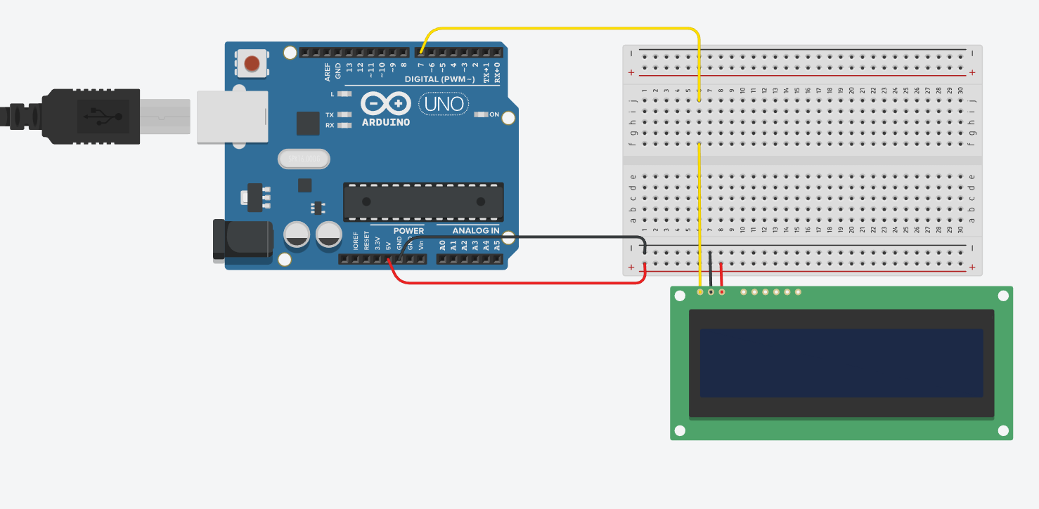
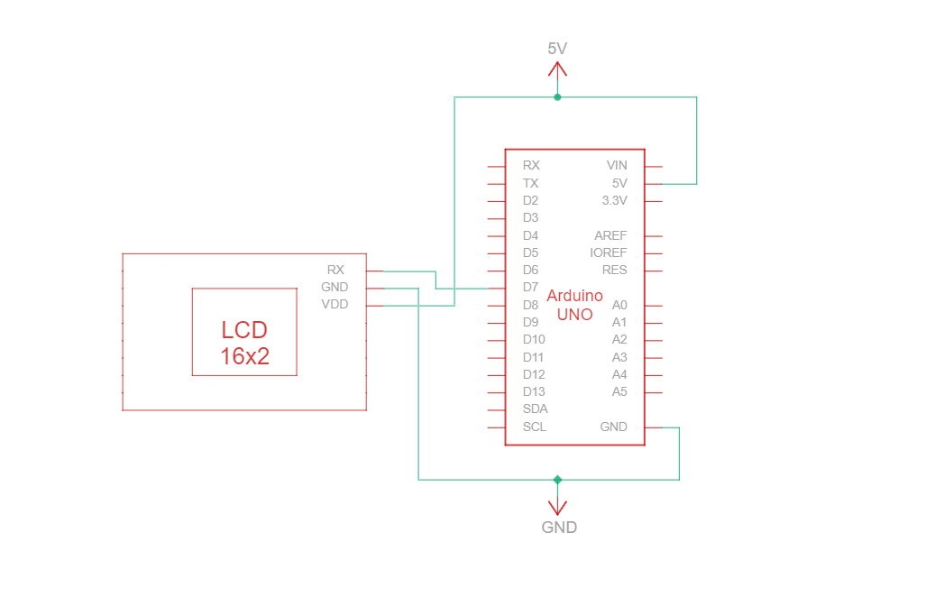
RS232 TTL è un protocollo di comunicazione seriale che utilizza specifiche di tipo RS232 ma con livelli logici TTL (da 0 V a Vcc, tipicamente 3,3 V o 5 V). Il circuito di connessione RS232 TTL tra Arduino e il display Newhaven a 16 caratteri utilizza solo tre fili:
| Arduino | LCD | Tipo di connessione |
|---|---|---|
| Pin 5V | Pin 3: V DD | Potenza |
| Perno di terra | Pin 2: Terra | Terreno |
| Pin 7: Pin I/O digitale | Pin 1: RX | Porta di ingresso seriale RS-232 (TTL) |
Nota:
R1 e R2 sul display devono essere aperti per abilitare RS232 TTL come specificato nella scheda tecnica.
Circuito di cablaggio RS232 TTL
Schema di cablaggio RS232 TTL
Abbiamo creato un tutorial dettagliato e adatto ai principianti su Instructables per la comunicazione RS232 TTL. Il tutorial include tutti i passaggi necessari per completare questo progetto. Dai un'occhiata qui: www.instructables.com/Arduino-LCD-Tutorial/
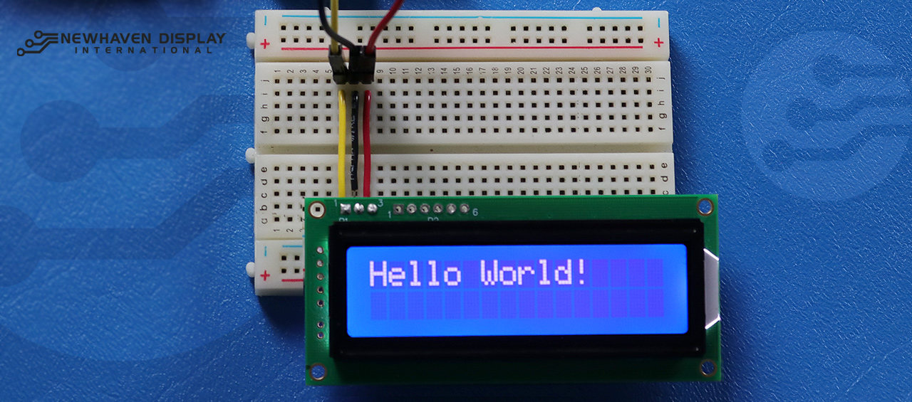
Arduino - LCD Hello World! Esempio di codice utilizzando la comunicazione seriale RS232 TTL
Il seguente esempio di codice visualizza "Hello Word!" sul display LCD utilizzando la comunicazione RS232 TTL.
NHD-0216K3Z-NSW-BBW-V3 ***************************************************** Questo codice è stato scritto per Arduino UNO utilizzando l'interfaccia RS-232. /* Riferimento cablaggio RS-232 per: NHD-0216K3Z-NSW-BBW-V3 --------------------------- LCD | Arduino --------------------------- 1(RX) --> 7 2(VSS) --> Terra 3(VDD) --> 5V */ #define P1 7 //RX il pin su cui ricevere i dati seriali. /***************************************************** Configurazione RS-232 per comandi e dati. Per ulteriori informazioni su RS-232, visitare il nostro Centro assistenza. /*****************************************************/ #include#define RxPin P1 SoftwareSerial NHD_LCD = SoftwareSerial(P1, RxPin); /***************************************************** Set LCD Contrast /*****************************************************/ void Set_Contrast() { NHD_LCD.write(0xFE); //Prefix command NHD_LCD.write(0x52); //Contrast command NHD_LCD.write(0x28); //Set contrast value delayMicroseconds(500); } /***************************************************** Clear LCD /*****************************************************/ void Clear_display() { NHD_LCD.write(0xFE); //Prefix command NHD_LCD.write(0x51); //Clear Display delayMicroseconds(1500); } /***************************************************** Set Arduino UNO IO ports as Output mode /*****************************************************/ void Set_Pins() { pinMode(RxPin, OUTPUT); } /***************************************************** Set LCD Backlight /*****************************************************/ void Set_Backlight() { NHD_LCD.write(0xFE); //prefix command NHD_LCD.write(0x53); //Backlight command NHD_LCD.write(0x08); //Set backlight value delayMicroseconds(100); } /***************************************************** Set cursor Mode = 0 sets Blinking cursor off Mode = 1 sets Blinking cursor on /*****************************************************/ void Set_Cursor(int mode) { NHD_LCD.write(0xFE); //Prefix command if (mode == 0) { NHD_LCD.write(0x4c); //Turn blinking cursor off } else if (mode == 1) { NHD_LCD.write(0x4b); //Turn blinking cursor on } delayMicroseconds(100); } /***************************************************** Write "Hello World!" to LCD /*****************************************************/ void Hello_World() { NHD_LCD.write(0x48); // H NHD_LCD.write(0x65); // e NHD_LCD.write(0x6C); // l NHD_LCD.write(0x6C); // l NHD_LCD.write(0x6F); // o NHD_LCD.write(0x11); // Blank NHD_LCD.write(0x57); // W NHD_LCD.write(0x6f); // o NHD_LCD.write(0x72); // r NHD_LCD.write(0x6c); // l NHD_LCD.write(0x64); // d NHD_LCD.write(0x21); // ! } /***************************************************** Main function /*****************************************************/ void setup() { NHD_LCD.begin(9600); //Sets 9600 Baud Rate the display can receive and transmit data at a rate of 9600 bits per second by default. delay(15); Set_Pins(); //Set IO ports Set_Cursor(0); //Turns off blinking cursor Set_Contrast(); //Set display Contrast Set_Backlight(); //Set display Backlight Clear_display(); //Clear display Hello_World(); //Display "Hello Wolrd!" } void loop() { }
Risoluzione dei problemi del tuo LCD - Progetto Arduino
Di seguito illustreremo alcuni passaggi comuni da seguire quando si incontrano difficoltà o problemi con il progetto Arduino - LCD.
- Controllare i collegamenti dei cavi: il problema più comune quando si collega un LCD ad Arduino è un cablaggio errato. Controllare i collegamenti dei cavi rispetto allo schema dei pin e al circuito forniti per garantire una connettività corretta. Inoltre, tenere presente che il NHD-0216K3Z-NSW-BBW-V3 può essere configurato per funzionare con interfacce SPI, I2C e RS232 TTL. Per funzionare con l'interfaccia SPI, è necessario saldare un resistore da 0 ohm sulla sezione R2 del PCB.
- Ispezionare i componenti: verificare la presenza di eventuali segni visibili di danneggiamento su Arduino, LCD o cavi di collegamento.
- Verifica il codice: assicurati che il codice caricato sul tuo Arduino sia corretto e privo di errori.
- Controllare l'alimentazione: assicurarsi che la fonte di alimentazione sia sufficiente per alimentare sia Arduino che il display LCD.
- Prova con un LCD funzionante: se continui a riscontrare problemi, prova a collegare un altro LCD funzionante al tuo Arduino. Questo ti aiuterà a determinare se il problema è dovuto all'LCD o alla scheda Arduino stessa.
- Regola il contrasto: Se avete difficoltà a vedere il testo visualizzato sul display LCD, provate a regolare il contrasto utilizzando la funzione del software.
Imposta_Contrasto(), descritto sopra. Condizioni di illuminazione diverse potrebbero richiedere impostazioni di contrasto diverse per una visibilità ottimale. - Controlla la versione dell'IDE Arduino: assicurati di utilizzare l'ultima versione dell'IDE Arduino. Le versioni obsolete potrebbero contenere bug o essere incompatibili con il tuo progetto.
- Prova le singole funzionalità: se riscontri problemi con funzionalità specifiche come lo scorrimento o il controllo del contrasto, prova a eseguire un codice più semplice come l'esempio "Hello World!" per isolare il problema. Questo può aiutarti a determinare se il problema è correlato al codice o all'hardware.
- Chiedi aiuto alla community: se non riesci a risolvere il problema dopo aver seguito i passaggi di risoluzione dei problemi sopra indicati, valuta la possibilità di chiedere aiuto alla community online. I forum online, come il Newhaven Display Support Forum,l'Arduino Stack Exchange o il forumArduino.cc, sono ottime risorse per ottenere assistenza da utenti esperti.
Seguendo questi passaggi per la risoluzione dei problemi, dovresti essere in grado di diagnosticare e risolvere la maggior parte dei problemi relativi al collegamento di un LCD a una scheda Arduino. Ricorda che la pazienza e l'attenzione ai dettagli sono fondamentali quando si risolvono i problemi dei progetti elettronici.
Risorse aggiuntive
- Sito ufficiale di Arduino UNO.
- Descrizione del prodotto LCD 16x2.
- Scheda tecnica e specifiche del prodotto LCD 16x2.
- Tutorial Instructables su Arduino-LCD adatto ai principianti
- Forum di supporto LCD caratteri.
- Leggi la nostra guida per principianti alla prototipazione dei display.
- Codice di esempio LCD caratteri.
- Scopri come proteggere i dispositivi elettronici dall'ESD.
- Scopri i diversi tipi di schermi LCD.
- Scopri le modalità LCD.